


What is a Multiplexer and How Does it Work? [Explained]

Multiplexers (also called MUXs or multiplexores) are combinational circuits that select one of several inputs and forward it to an output. Digital or analog inputs can be used with a multiplexer. As well as multiplexers, data selectors also exist. It is useful to use multiplexers to transmit large amounts of data quickly and over a wide network. A transistor-relay multiplexer is called an analog multiplexer and is used in analog applications, whereas a logic gate multiplexer is a digital multiplexer and is used when digital applications are involved. A demultiplexer is the opposite of a multiplexer.
What is Multiplexer?
Multiplexers receive signals from multiple acquisition networks using multiple inputs and one output. A microprocessor receives, processes, transmits, and controls all input signals, as well as controlling the entire system as it receives and processes data.
The multiplexing process involves sequentially channeling multiple signals to one digital converter. In this way, the number of channels can be increased at a low cost. Using just one A/D converter to process multiple inputs allows a multiplexer to reduce cost significantly. A multiplexer consists of a set of switches. Multiplexers, then, are circuits or devices that allow a single transmission channel to be shared among multiple transmission channels.
One input can communicate with only one output through a selector pin. Using the sampling theorem applicable to the given signal, the control unit scans all inputs sequentially and reads them at the same rate. Multiplexers increase the amount of data you can send over a network in a specific period of time at a given bandwidth.
How Does a Multiplexer Work?
The workings of a multiplexer are shown below.
-
Inputs: Input lines of a multiplexer are usually represented as binary values. A multiplexer's input number depends on its specific design and is generally a power of two (e.g., 2, 4, 8).
-
Control signals: Multiplexers also have control inputs for selecting and forwarding input signals. Inputs can be represented by binary values and the number of control inputs is determined by the number of inputs.
-
Selection: An output signal is selected based on the input signals specified through the control inputs. Control inputs are selected based on their binary values.
-
Output: Signals are multiplexed and appear as output signals after passing through the multiplexer. Data is sent from the selected input to the output line.
Types of Multiplexer
Listed below are types of multiplexers that are commonly used:
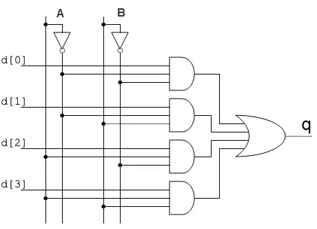
4-1 Multiplexer
Using AND gates, the 4-1 multiplexer selects an input bit dynamically based on AB values for each of the four input bits (0, D1, D2, D3). For instance, with AB=00, higher AND gates are activated, which transmit data from D0 to q. ICs such as 74153 and 45352 embody this versatile circuit. The 4-1 multiplexer provides a diverse input selection and corresponding output transmission based on control bit values by transforming AB to 11 and deactivating higher gates, transmission of D3 to 'q'.
4-1 Multiplexer
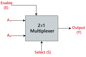
2-1 Multiplexer
Two input channels can be selected via a select line. Once the input has been selected, the output line is directed to the chosen input. Basically, it allows a user to select between two different data sources in a digital circuit. An 2-1 multiplexer has two inputs, labeled A0 and A1, and one selection line, S0. A single output line, Y, is present on the multiplexer. It is possible for one of the two inputs to be linked to the output depending on which combinations of inputs are present at the selection line S0. Here is a block diagram for a 2-1 multiplexer.
2-1 Multiplexer
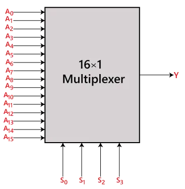
16-1 Multiplexer
With four select lines, the 16-1 multiplexer can select and route data from sixteen different input channels, making it capable of handling a broader range of input channels. This type of multiplexer can handle data in a comprehensive manner for applications with a significant number of input options. It consists of 16 inputs (A0, A1, ..., A15), 4 selection lines (S0, S1, S2, S3), and a single output (Y). Connections between output lines S0, S1, and S2 are determined by the combination of inputs at selection lines S0, S1, and S2. A 16-input system links its output to a 16-output system based on this combination. Based on selected combinations of control lines, the 16-1 multiplexer can selectively transmit inputs to outputs in the form of the block diagram and truth table.
16-1 Multiplexer
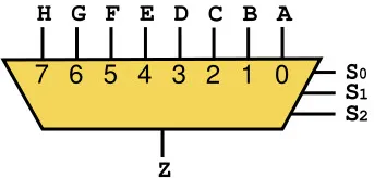
8-1 Multiplexer
Three select lines are available on the 8-1 multiplexer, which can handle eight input channels. As a result, digital systems are able to control data streams more effectively. There are 8 inputs, one output, and three selection lines, so it is common in situations that require diverse inputs. Based on select line combinations, it utilizes 8 AND gates and an OR gate. The output of a specific AND gate is 1 when a select line is activated, while the output of others is 0. Digital circuit data routing relies on the OR gate to consolidate these outputs and ensure accurate selection.
8-1 Multiplexer
Data multiplexer
Data is received via one input and output via several outputs in a MUX with multiple selection inputs. A combination of selection bits is used to select inputs. By using a data MUX, multiple data streams can be combined into one output stream.
Analog multiplexer
In MUXs, the common output is obtained by selecting an analog input from several analog inputs. Audio and video signals can be switched using analog MUXs.
Uses of a Multiplexer
In the context of communication and digital systems, multiplexers are commonly used. A few examples follow.
Digital communication: A multiplexer combines multiple data streams on a transmission channel so that they can be transmitted at high speeds. Multiple input signals from different sources are combined in time-division multiplexing (TDM), with each input signal assigned a specific time slot for transmission.
Data routing: It is possible to route data from multiple sources by using multiplexers. The input data streams can be chosen to be forwarded to the desired output port in network switches and routers, for example.
Memory addressing: In digital systems with memory components, multiplexers are used to address memory. When reading or writing data to memory modules, they help select the memory address. By routing memory address signals based on control signals, they facilitate the loading of memory modules.
Arithmetic logic units (ALUs): An ALU, which is an essential component of a processor, often includes multiplexers. ALUs use control signals to determine what arithmetic or logical operation should be performed on input data.
Analog-to-digital conversion (ADC): ADC converts analog signals into digital signals by multiplexing them. Multiple analog signals can be converted using a single analog-to-digital converter by sequentially connecting each analog input channel to it.
Advantages of Multiplexer
Due to their numerous advantages, multiplexers play a crucial role in digital circuits. The following are some advantages of multiplexers:
-
Cost and Complexity Reduction: Multiple inputs are combined into a single output, simplifying system architecture, as well as reducing manufacturing costs and materials. Multiplexers have this core advantage.
-
Multiple Input Signal Integration: As a result, multiple input signals can be integrated into a circuit to create diverse combination circuits for a variety of applications.
-
Elimination of K-Maps and Simplification: Multiplexers operate without Karnaugh maps, simplifying circuit design and promoting an efficient, straightforward process of circuit implementation. Multiplexers do not have as many advantages as it does.
-
Low Heat Dissipation: Analog switching currents typically range from 10mA to 20mA, which minimizes heat dissipation.
-
Simplification of Logic Design: By taking multiple inputs into consideration and directing them to a single output, it streamlines, streamlines, and simplifies logic design in digital systems.
Combination circuits can benefit from multiplexers, which improve system reliability, flexibility, and reduce wire complexity and costs.
Disadvantages of Multiplexer
It is important to recognize multiplexers' inherent limitations and drawbacks in circuitry, regardless of their benefits. Multiplexers have the following disadvantages:
-
Propagation Delays: The inclusion of multiplexers in switching ports and I/O signals introduces additional delays. Data transmission speed and efficiency can be affected by these delays, which originate from the internal processes of the multiplexer.
-
Port Simultaneous Usage Limitations: Multiplexers have inherent limitations on the simultaneous use of ports. Due to this limitation, it is possible that the system will be limited in its ability to handle multiple data streams concurrently.
-
Increased Firmware Complexity: It may be necessary to introduce complex firmware to handle port switching in a multiplexer. Management of port switching is complicated, especially in scenarios with many inputs, making firmware implementation more complex.
-
Control Overhead: An additional I/O port is often required to control a multiplexer. Data selection and transmission are handled by these ports, but they also add overhead to the system, potentially reducing its efficiency.
Multiplexer Design and Architecture
Depending on the number of inputs, outputs, and control lines, a multiplexer is designed differently. Activating the control line enables each input line to be transmitted to the output, which corresponds to a binary code on the input line. To form the basic structure of a multiplexer, AND, OR, and NOT gates are most commonly used.
Integration with Other Digital Devices
Various digital devices can be integrated with multiplexers to provide a multitude of functions. To manage bidirectional data flow, multiplexers and demultiplexers are commonly integrated into communication systems. Data transmission systems also use them in conjunction with encoders and decoders to efficiently convert signals and route them.
Future Trends
The role of multiplexers is bound to grow even more important with the exponential growth of data traffic and digital communications. Eventually, multiplexers may be developed that are more advanced and efficient, capable of integrating with other digital systems and handling larger data inputs.
Final Verdict
The Multiplexer serves as an essential component of modern communication and electronics, enabling cost-effective and efficient data transmission. In addition to routing data, they also implement advanced hardware and manage memory, making them versatile components. Continuous innovation in multiplexer technology is driven by the evolving digital world, making it an important area for future advancements to watch.
Multiplexers reveal the mechanisms that enable our day-to-day digital interactions as well as provide insight into the fascinating field of data communication. Multiplexers are the unsung heroes of the digital world, playing a silent yet indispensable role from networking infrastructure to hardware in our personal devices.


