


Types of 547 Transistors:All Explained
Welcome everyone to Blikai Electronics, your go-to place for electronic knowledge and insights. I'm your host, Phoebe. Today, I'll be sharing information about the BC547 transistor.
What is the BC547 transistor?
.webp)
The BC547 is an NPN bipolar junction transistor (BJT) consisting of three terminals: the emitter (E), collector (C), and base (B). When a small current is applied to the base terminal, it can control a larger current flow between the collector and emitter terminals.
This transistor is commonly used for current amplification and switching purposes, with a maximum current gain of 800.
Pin configuration of the BC547 transistor
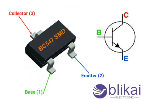
| Pin Number | Pin Name | Pin Description |
| 1 | Collector | Current flows through the collector terminal. |
| 2 | Base | This pin controls the transistor’s biasing. |
| 3 | Emitter | Current flows into the transistor through the emitter terminal. |
BC547 transistor CAD model
BC547 Transistor Circuit Model
.webp)
BC547 Transistor Package Model
.webp)
BC547 Transistor Package Model
.webp)
Specifications and characteristics of the BC547 transistor
- Transistor Type: NPN
- DC Current Gain (hFE) = 800
- Continuous Collector Current (Ic) = 100mA
- Emitter-Base Voltage (VBE) = 6V
- Maximum Base Current (IB) = 5mA
- Transition Frequency = 300MHz
- Power Dissipation = 625mW
- Package Type: TO-92
- Maximum Storage and Operating Temperature: -65 to +150°C
Working principle of the BC547 transistor
When an input voltage is applied to the base terminal, a certain amount of current begins to flow from the base terminal to the emitter terminal, controlling the current at the collector terminal. The voltage between the base and emitter terminals (VBE) is negative at the emitter and positive at the base, which is typical for its NPN structure. The voltage between the collector and base terminals (VCB) is negative at the base and positive at the collector. Similarly, the voltage between the collector and emitter terminals (VCE) is negative at the emitter and positive at the collector.
BC547 Transistor Terminal Voltage Polarity
When an input voltage is applied to the base terminal, a certain amount of current begins to flow from the base terminal to the emitter terminal, controlling the current at the collector terminal. The voltage between the base and emitter terminals (VBE) is negative at the emitter and positive at the base, typical for its NPN structure. The voltage between the collector and base terminals (VCB) is negative at the base and positive at the collector, and the voltage between the collector and emitter terminals (VCE) is negative at the emitter and positive at the collector.
.webp)
Operating states of the BC547 transistor
The operating states or modes of the BC547, like all other transistors, fall into three regions:
- Amplification Region
- Saturation Region
- Cutoff Region
Here are the three operating regions of the BC547 transistor:
.webp)
(a) Amplification Region
The amplification region lies between the cutoff and saturation regions. In this active region, the transistor’s emitter junction is forward biased, while the collector junction is reverse biased. Here, the collector current is β times the base current, which can be expressed as:
IC = β IB
where:
IC = Collector current
β = Current gain factor
IB = Base current
Therefore, the increase in collector current is directly proportional to the base current.
(b) Saturation Region
In this region, the transistor operates like a short circuit. The collector and emitter currents reach their maximum values. In the saturation region, both the emitter junction and the collector junction are forward biased. In other words, the transistor acts as a closed switch or a short circuit carrying maximum current, meaning:
IC = IE
where:
IC = Collector current
IE = Emitter current.
(c) Cutoff Region
In this region, the transistor acts as an open switch or an open circuit. The collector, emitter, and base currents are all zero. In the cutoff region, both the emitter junction and the collector junction are reverse biased. Since the collector, emitter, and base currents are zero in this region, it can be expressed as:
IC = IE = IB = 0
where:
IC = Collector current
IE = Emitter current
IB = Base current
Application circuits for the BC547 transistor
BC547 Transistor as a Switch
The regions where the transistor functions as a switch are the saturation region and the cutoff region. When we apply a sufficiently high current to the base of the transistor, it provides a path for the collector current to flow through the base to the emitter.
To use the transistor as a switch, it must be driven into saturation with enough base current. In the saturation region, the transistor operates as a closed switch.
1) Principle of the Transistor as a Closed Switch
.webp)
Once the positive signal (in the form of voltage and current) on the transistor's base is removed, the current between the collector and emitter becomes zero, and the transistor behaves like an open switch in the cutoff region.
2) Principle of the Transistor as an Open Switch
This simply means that if we apply a signal (voltage/current) between the collector and emitter instead of between the base and emitter, the transistor will not operate. However, a small signal at the base is sufficient to make it work.
3) BC547 Transistor in Switch Applications
Let’s see how the transistor operates as a switch. When a positive signal (+) is applied to its base, it provides a path for the collector current to flow from the base to the emitter. This is how it works—by allowing current to pass through while the collector’s signal is bypassed under base conditions.
When we press the button, the BJT’s base receives a signal (in the form of voltage and current), which then allows current to flow from the collector to the emitter. The current can flow through the circuit as follows (with electrons flowing in the opposite direction):
Power (+5V) → Resistor 280 Ω → LED → Collector-Base-Emitter → Ground
This simply means that if we apply a signal (voltage/current) between the collector and emitter instead of to the base, the transistor will not work. However, a small signal at the base is enough to make it function.
.webp)
Pressing the button here will light up the LED because the circuit is now completed from the power source to ground.
4) ON/OFF Touch Switch Using the BC547
The ON/OFF touch switch using the BC547 transistor is shown in the diagram below. Once power is supplied to the circuit, it becomes activated. With the circuit powered, the relay operates in the closed mode. This keeps the base of the Q3 transistor at a high level due to the effect of the R7 resistor, maintaining the cutoff state.
.webp)
When switch S2 is opened, the Q4 transistor will begin conducting, allowing the relay "L3" to latch. The base terminal of the Q3 transistor will be pulled low, causing the L2 LED to flash, indicating that the power is on. Q4 transistor conducts because the voltage at the collector terminal of transistor Q3 is influenced by the R8 resistor.
When switch S1 is pressed momentarily, the base of transistor Q3 is pulled high, causing L2 to turn off because the base of Q4 transistor is pulled down through the R8 resistor, thus deactivating the relay L3.
2. BC547 Transistor as an Amplifier
1) Principle of the BC547 Transistor as an Amplifier
It’s a common misconception that amplifiers can boost any signal to any level, but in practice, this isn’t the case. Here are three key points to remember:
- The transistor cannot amplify the power supply voltage \( V_c \).
- The transistor can only amplify the voltage signal present at its base to the maximum amplitude of the applied \( V_{cc} \) voltage.
This is similar to bypassing a signal with the same waveform but higher amplitude (voltage).
.webp)
The transistor acts as an amplifier by increasing the strength of a weak signal applied to its base. The transistor operates as an amplifier in the active or linear region. The diagram below shows how to use the transistor as an emitter amplifier.
2) BC547 Transistor in Amplifier Applications
In this region, as the base current increases, the collector current also increases proportionally according to the formula:
IC = β IB
where:
IC = Collector current
β = Current gain factor
IB = Base current
Therefore, a small input signal results in a large output, meaning the transistor is functioning as an amplifier.
Suitable replacements for the BC547 transistor
1. BC547 Complementary PNP
The complementary PNP models for the BC547 are the BC557 and BC558.
2. BC547 Substitutes and Equivalents
You can replace the BC547 with BC548, BC549, 2N2222, 2N3904, 2N4401, or BC337. Some of these transistors have different pin configurations from the BC547, so be sure to check the pin configuration before replacing them in a circuit.
3. BC547 SMD Equivalents
SMD equivalents for the BC547 include the BC847, BC847W, BC850, and BC850W.
Common applications of the BC547 transistor
- Current Amplification
- Audio Amplifiers
- Switch Loads < 100mA
- Darlington Pairs
- LED Drivers, Relay Drivers, and Other Drivers
- Amplifiers for Audio, Signal, etc.
- Darlington Pairs
- Fast Switching
- PWM (Pulse Width Modulation)
- Alarm Circuits
- LED Flashing Circuits
- Water Level Indicators
- Sensor-Based Circuits
- Audio Pre-Amplifier Circuits
- RF Circuits
- Touch Switch Circuits
- Thermal Circuits
- Humidity Alarms
- Latching Circuits
- Street Light Circuits
- Single-Channel Relay Drivers
- Volume Indicators
Related Articles
BC338 NPN Transistor: Features, Applications, and FAQ
2N4401 NPN Transistor: Datasheet, Applications, and Features
2N5551 Transistor:Features,Applications and Pinout


