


How does an Accelerometer Work?
A accelerometer is a device designed to gauge the linear acceleration of a moving object. It comprises a proof mass (also referred to as a sensitive mass), support, potentiometer, spring, damper, and housing. Notably, the accelerometer employed for assessing aircraft overload stands out as one of the earliest instruments utilized in aviation.
A accelerometer is a device that identifies the vibrations or accelerations in the movement of a structure. Vibrations or changes in motion (acceleration) cause compression in the piezoelectric material, generating a charge proportional to the applied force. The relationship between charge and acceleration arises from the proportional nature of charge to force, with mass remaining constant. Accelerometers are now ubiquitous on nearly all smartphones. They are utilized to detect specific movements of the phone and contribute to functions like automatic screen brightness adjustments when the phone is flipped over. In industrial settings, accelerometers assist engineers in comprehending machinery stability by identifying forces or vibrations that should not be present.
Ⅱ. How does a accelerometer do?
Accelerometers differentiate between static and dynamic forces. Forces like gravity or friction, which remain constant, are categorized as static acceleration. These forces are generally predictable and uniform, exemplified by the constant acceleration of gravity at 9.8 m/s, prevalent everywhere on Earth.
Non-uniform dynamic acceleration forces, such as vibration and shock, are illustrated by events like a car accident. Here, the acceleration undergoes a sudden change compared to the previous state. Accelerometers function by detecting acceleration and transforming it into a measurable quantity, typically an electrical signal.
Ⅲ. Types of accelerometers
Accelerometers are categorized into four types based on their operational principles:
Piezoelectric accelerometer
Piezoelectric accelerometers leverage the piezoelectric effect exhibited by certain crystals.
In this effect, when specific crystals undergo deformation in a particular direction due to a force, polarization occurs within them, resulting in the creation of opposite-sign charges on their two surfaces. Once the external force is removed, the crystals return to an uncharged state. This phenomenon is known as the "piezoelectric effect."
Commonly used piezoelectric crystals include quartz, piezoelectric ceramics, and others with a piezoelectric effect. The force applied by the mass on the piezoelectric element changes during the accelerometer's vibrations. This force alteration is proportionate to the recorded acceleration when the measured vibration frequency is significantly lower than the accelerometer's natural frequency.
In the designations, S represents spring, M represents mass, B denotes base, R is the clamping ring, and P stands for the piezoelectric element.
Figure a illustrates a compression type with a centrally positioned piezoelectric element-mass-spring system mounted on a circular central pillar attached to the base. Although this structure has a high resonance frequency, the connection of base B to the test object can directly influence the output of the vibration pickup due to deformation in the base B. Changes in the test object and ambient temperature can also impact the piezoelectric element, altering the preload force and leading to temperature drift.
Figure b displays an annular shear type, where the piezoelectric element is clamped on a triangular center column by a clamping ring. During axial vibration, the piezoelectric element experiences shear stress. This design provides effective base deformation and isolation from temperature changes, along with a high resonance frequency and strong linearity.
Figure c depicts a triangle shear form with a simple construction suitable for a compact high-resonance-frequency accelerometer. However, its maximum operating temperature is limited as the binder softens with temperature rise.
Piezoelectric accelerometers are characterized by a large dynamic range, wide frequency range, robustness, durability, minimal external interference, and the ability of the piezoelectric material to generate a charge signal without an external power supply. They are the most prevalent vibration sensors in the market.
Despite the simplicity and historical commercial use of piezoelectric accelerometers, their performance indicators are closely tied to material properties, design, and processing technology. Consequently, the actual parameters of performance, stability, and consistency can vary significantly among similar sensors in the market. One notable drawback of piezoelectric accelerometers compared to piezoresistive and capacitive accelerometers is their inability to measure zero-frequency impulses.
Piezoresistive accelerometer
The inaugural silicon micro-accelerometer introduced was the piezoresistive accelerometer, developed using MEMS silicon micromachining technology. The elastic component in a piezoresistive accelerometer typically comprises a silicon beam and a mass block supported by a cantilever beam. Resistors are created and interconnected to form measurement bridges. As the mass block moves up and down under inertial force, the stress-induced changes in resistance on the cantilever beam lead to variations in the output voltage of the measurement bridge, facilitating the measurement of acceleration.
Piezoresistive silicon micro-acceleration sensors are available in various structural configurations, such as cantilever beams, double-arm beams, 4-beams, and double-island-5 beams. The sensitivity, frequency response, range, and other characteristics of the sensor are dictated by the structural design and dimensions of the elastic element. Introducing a mass block can enhance tension on the cantilever beam during reduced acceleration, thereby improving the sensor's output sensitivity.
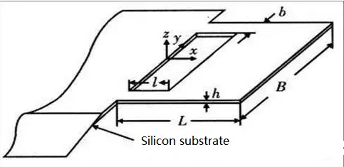
Under conditions of high acceleration, the action of the mass block may subject the cantilever beam to stress exceeding the yield stress, leading to breakage due to excessive deformation. To address this, a structural design featuring a single-arm beam and double-arm beam with equal mass block and beam thickness is proposed for high-gn value acceleration, as illustrated in the diagram.
The piezoresistive accelerometer, leveraging cutting-edge MEMS silicon micromachining technology, stands out as a compact and energy-efficient device. Its seamless integration into diverse analog and digital circuits makes it a preferred choice in various applications, including automotive crash tests, test instruments, and equipment vibration monitoring.
The strain-sensitive core of the piezoresistive accelerometer is constructed using a semiconductor material, forming a resistance measuring bridge, while its dynamic structural model remains a spring-mass system.
Recent advancements in microfabrication manufacturing technology have enhanced the flexibility in designing piezoresistive form-sensitive cores to cater to diverse measurement needs. These accelerometers exhibit a wide range of sensitivities and can capture anything from low-sensitivity, high-range shock readings to high-sensitivity, low-frequency DC observations.
Additionally, the measurement frequency range of piezoresistive accelerometers spans from DC signals to high frequencies with high stiffness, covering a range of tens of kilohertz. Notably, their ultra-miniaturized design is a standout feature. It's crucial to acknowledge that, while piezoresistive sensing cores offer versatility in design and application, their applicability for a specific design may be narrower compared to piezoelectric sensors.
Temperature sensitivity is a notable challenge for piezoresistive acceleration sensors, often requiring temperature adjustments in practical applications. In terms of cost, piezoresistive sensors produced in large quantities are cost-effective, but the manufacturing cost for sensitive cores tailored for specific applications can be significantly higher than that of piezoelectric acceleration sensors.
Capacitive accelerometer
Capacitive accelerometers employ the capacitance principle to offer sensors with variable capacitance based on polar distance. One electrode remains stationary, while the other constitutes an elastic diaphragm that undergoes changes. The capacitance fluctuates as external forces (air pressure, hydraulic pressure, etc.) displace the elastic diaphragm. This sensor is adept at measuring airflow (or liquid flow) vibration velocity (or acceleration) as well as pressure.
Characterized by a straightforward circuit structure, a broad frequency range of approximately 0-450Hz, linearity below 1%, high sensitivity, reliable output, limited temperature drift, minimal measurement error, steady-state response, low output impedance, and an output power equivalent to the relational formulation of vibration acceleration, capacitive accelerometers offer simplicity and ease of calculation, finding applications across a wide range of scenarios.
Nevertheless, the nonlinearity of the signal's input and output, limitations in range, susceptibility to cable capacitance, and the high-impedance nature of capacitive sensors often necessitate subsequent circuitry to enhance the output signal. While capacitive accelerometers are commonly used for low-frequency measurements in practical applications, their adaptability falls short of piezoelectric accelerometers, and their cost is significantly higher.
Capacitive accelerometers, also known as capacitive accelerometers, are widely employed in various industries, including airbags, mobile phones, and other mobile devices, where there is no comparable alternative. Leveraging Microelectromechanical Systems (MEMS) in their design, capacitive accelerometers become cost-effective in mass production, leading to reduced overall costs.
Feedback Accelerometer
When the mass block experiences displacement from its static equilibrium position due to acceleration input through the accelerometer shell, the displacement sensor detects this movement. The detected displacement signal is then amplified by the servo amplifier, resulting in a current output. This current flows through the electromagnetic coil and enters the magnetic field of the permanent magnet, generating an electromagnetic restoring force at the center. This force compels the mass block to return to its original static equilibrium position, creating a closed-loop system where the sensor emits an analog signal proportional to the acceleration value.
A servo accelerometer is characterized by a closed-loop test system with robust dynamic performance, a broad dynamic range, and excellent linearity. The operational concept involves the sensor's vibration system forming an "mk" system, similar to a conventional accelerometer but with an electromagnetic coil coupled to the mass "m." Acceleration causes the mass block to deviate from the equilibrium position, and the amplified displacement, detected by the displacement sensor, is converted into a current output. The closed-loop operation is maintained as the current generates an electromagnetic restoring force in the permanent magnet's magnetic field, striving to return the mass block to its original equilibrium position within the instrument housing.
The feedback effect enhances anti-interference capabilities, improves measurement precision, and expands the measurement range. Servo acceleration measuring technology is widely employed in inertial navigation, inertial guidance systems, and high-precision vibration measurement and calibration.
Three-Axis accelerometer
Built upon the acceleration principle, the three-axis accelerometer is designed to measure acceleration vectors in space accurately. It necessitates measuring the components along the three coordinate axes of an object to precisely understand its motion state.
The three-axis accelerometer can achieve double-axis ±90 degrees or double-axis 0-360 degree inclination, relying on the theory of gravity. Adjusted for higher accuracy, a single-axis accelerometer has a measuring angle greater than 60 degrees.
Modern three-axis accelerometers predominantly incorporate the working principles of piezoresistive, piezoelectric, and capacitive accelerometers. The resulting acceleration is proportionate to changes in resistance, voltage, and capacitance, collected through amplification and filter circuits.
Compact and lightweight (in grams), the three-axis accelerometer excels in monitoring acceleration in space and accurately reflecting object motion features. Its applications span aerospace, robotics, automotive, and medical fields.
Ⅳ. Primary Applications of accelerometers
accelerometers, or accelerometers, find extensive applications in both daily life and various industrial sectors.
Digital Devices:
Accelerometers embedded in smartphones and digital cameras facilitate automatic display rotation based on the device's orientation.
Vehicles:
In the automotive industry, accelerometers play a crucial role in airbag deployment. The sensor detects signals during violent shocks, prompting the accelerometer to trigger the airbag, contributing to countless lives saved.
Drones:
Accelerometers are essential for drones, assisting in maintaining their direction during flight.
Rotating Machinery:
Detecting undulating vibrations in rotating machinery, accelerometers contribute to monitoring and maintenance.
Industrial Platforms:
Used to check the stability or inclination of platforms in industrial settings.
Vibration Monitoring:
Accelerometers are increasingly utilized in industrial plants, turbines, and other machinery to monitor vibrations, preventing potential damage.
Ⅴ. Operational Characteristics of accelerometers
Understanding the operational parameters of accelerometers is essential for accurate and effective usage.
Sensitivity:
Measured in millivolts per gram (mv/g), sensitivity indicates the output voltage in response to acceleration. It is crucial for gauging the amplitude of monitored vibrations.
Frequency Response:
Represents the maximum variance of sensitivity over a frequency range. Nominal and real sensitivity are often evaluated at a specific frequency.
Temperature Output Sensitivity:
Reflects the change in output voltage concerning temperature variations. It ensures the accelerometer's stability under different temperature conditions.
Power, Voltage:
Specifies the maximum and minimum input voltages to prevent damage. Overvoltage can lead to sensor destruction.
Temperature Range:
Indicates the operating and storage temperature limits for proper functionality.
Resonance Frequency:
The frequency at which the accelerometer exhibits the highest sensitivity in its frequency response.
Electrical Noise:
Describes the electronic noise generated by the amplifier circuit, influencing the overall accuracy of measurements.
Peak Amplitude:
Represents the highest vibration amplitude that the sensor can measure before amplifier distortion.
Ⅵ. Installation of accelerometers
Ensuring accurate and reliable data requires careful installation of accelerometers. Various methods are available for different applications:
Screw Installation:
Involves drilling holes and tapping screws along the axis of the vibration source, providing a stiff installation with a frequency response similar to the original calibration.
Adhesive Installation:
Utilizes adhesives such as epoxy resin, double-sided tape, or plasticine when drilling is not possible. The use of adhesives impacts the frequency response and is suitable for low-frequency fields.
Magnetic Base:
Offers portability without damaging the measured object. However, the magnetic base limits the accelerometer's frequency response.
Mica Sheet/Tetrafluoro Film:
Provides heat insulation and insulation, with mica and tetrafluoro being ideal materials for insulating the specimen from the accelerometer.
Three-Way Sensor Installation:
Allows for screw through-hole installation, side thread for inspection, or testing purposes.


