


Push-pull Amplifier :Overview and Working Principle
As the demand for long-distance audio communication grew, there arose a necessity to boost the amplitude of electrical signals for transmission over extended distances. Sectors such as telecommunications, including telephone and telegraphy, as well as duplex transmission, explored various methods to amplify signals, yet yielded unsatisfactory results. It wasn't until around 1912 that amplifiers made their debut, offering a solution to this challenge. Amplifiers are devices engineered to enhance the power of an input signal. Early amplifiers relied on vacuum tubes, which eventually gave way to transistors in the 1960s. There exists a plethora of amplifier types, distinguished by the active circuits employed in their design, as well as their operational characteristics. Among these, the power amplifier stands out, tailored to augment the power delivered to the load. A prominent example of a power amplifier is the push-pull amplifier.
What is Push-pull Amplifier?
A Push-pull Amplifier is a category of power amplifier characterized by the presence of a pair of active devices, typically comprising a complementary duo of transistors. In this configuration, one transistor delivers power to the load from the positive power supply, while its counterpart sinks current from the load to the ground.
Compared to single-ended class-A amplifiers, push-pull amplifiers boast higher efficiency. The transistors within this amplifier operate in anti-phase, ensuring that the difference between their outputs is fed to the load. Consequently, even-order harmonics inherent in the signal are suppressed, diminishing distortion stemming from non-linear components.
The nomenclature "push-pull" stems from the operation of these amplifiers: one transistor pushes current in one direction, while the other pulls current in the opposite direction. In a push-pull amplifier, one transistor functions during the positive half of the signal cycle, while its counterpart operates during the negative half.
Circuit Schematic
The circuitry of the push-pull amplifier is comprised of two active devices, namely an NPN and a PNP transistor, operating in an anti-phased manner. During the positive half cycle of the signal, one transistor becomes forward biased, while its counterpart activates during the negative half cycle. A center-tapped coupling transformer T1 is employed at the amplifier's source to split the input signal into two identical signals, each 180 degrees out of phase.
This amplifier can be configured in various arrangements, including Class-A, Class-B, and Class-AB push-pull configurations. The circuit designs for these classes exhibit differences in their construction and operation.
Schematic for Class-A Push-pull Amplifier
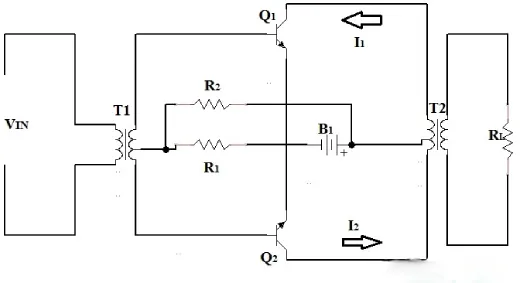
The Class-A push-pull amplifier configuration features a pair of identical transistors, denoted as Q1 and Q2. The emitter terminals of these transistors are joined together, establishing a common connection. Biasing for the transistors is achieved through resistors R1 and R2. During signal operation, one transistor must be forward-biased during the positive half-cycle, while its counterpart is activated during the negative half-cycle.
The collector terminals of Q1 and Q2 are linked to the respective ends of the primary winding of the output transformer T2. The base terminals of these transistors are interconnected with the secondary winding of the input transformer T1. The power supply is positioned between the center tap of the primary winding of T2 and the emitter junction of Q1 and Q2.
The load is connected to the secondary winding of transformer T2. Quiescent current flowing through Q1 and Q2 traverses in opposite directions through the halves of the primary winding of T2, effectively neutralizing magnetic saturation within the circuit.
class-a-push-pull-amplifier
Schematic for Class B Push-pull Amplifier
In the Class-B push-pull amplifier, biasing resistors R1 and R2 are absent. Both transistors operate at their cut-off points, where they consume minimal power under ideal conditions. Consequently, the efficiency of the Class-B push-pull amplifier surpasses that of the Class-A counterpart.
Circuit Diagram of Class AB Push-pull Amplifier
The Class-AB push-pull amplifier resembles the Class-A configuration, with adjustments made to biasing resistor values. Here, transistors Q1 and Q2 are biased slightly above their cut-in voltages, minimizing the duration during which both transistors are simultaneously turned off. This optimization diminishes crossover distortion in the Class-AB amplifier.
Working Principle of Push-pull Amplifier
The output stage of the amplifier is equipped to drive current in both directions through the load. Featuring two anti-phased transistors, Q1 and Q2, the input coupling transformer T1 divides the signal into two identical halves, each 180 degrees out of phase. During the positive half-cycle, one transistor becomes forward biased and conducts current, while its counterpart remains reverse biased. This polarity is reversed during the negative half-cycle.
Collector currents I1 and I2 from Q1 and Q2 flow in the same direction through corresponding halves of the primary winding of transformer T2. This induces an amplified output signal in the secondary winding of T2, where the current through the secondary is the difference between the collector currents of the transistors.
Advantages:
The Push-pull amplifier's output is derived from the variance in collector currents between its two transistors, effectively eradicating output harmonics and minimizing distortion. Additionally, this configuration offers heightened efficiency in Class B operation, accommodating constrained power supplies. With straightforward circuitry, Class-B amplifiers ensure that their output is devoid of even harmonics, while Class AB variants mitigate crossover distortion.
Applications:
Push-pull amplifiers find utility across diverse domains:
1. RF systems employ them for signal amplification.
2. Their affordability and compactness make them ideal for integration into digital systems.
3. They serve as audio amplifiers in various consumer electronics like TVs, mobile phones, and computers.
4. In long-distance communication systems necessitating low distortion, push-pull amplifiers are indispensable.
5. Loudspeakers benefit from their utilization.
6. They are integral to the amplification of radio frequency signals.
7. Power electronic systems rely on push-pull amplifiers for effective operation.
FAQs:
1) What is the rationale behind the nomenclature "Push-pull Amplifier"?
This amplifier incorporates a pair of transistors within its circuitry. During the positive half-cycle of the input signal, one transistor pushes current toward the output, while during the negative half-cycle, the other transistor pulls current toward the output. Consequently, the amplifier earns its name as a Push-pull Amplifier.
2) Can you elucidate the concept of a Complementary Push-pull Amplifier?
To circumvent the bulkiness associated with using a transformer in push-pull amplifier designs, a complementary approach is adopted. Here, two transistors—a NPN and a PNP—complement each other at the input stage, thus eliminating the need for a transformer. This configuration is termed as the Complementary Push-pull Amplifier.
3) What exactly entails the term "Push-pull"?
The push-pull output stage is constructed with a duo of complementary transistors, which alternately supply and absorb current from the load.
4) Why opt for a Push-pull Amplifier?
Push-pull amplifiers are favored for their ability to amplify signals without introducing distortion.
5) Which amplifier boasts the highest efficiency?
The Class B Push-pull Amplifier stands out with an efficiency rating of 78.9%.
The primary function of an amplifier is to increase the amplitude or power level of an input signal without distorting its waveform, thereby enabling the signal to be transmitted over longer distances or to drive a load such as a speaker or antenna with sufficient strength for effective operation.
Related Articles
What is TL074 Operational Amplifier?
Microprocessor Vs Integrated Circuit: What’s the Differences?


