


Resistor Symbol Explained: Types, Circuit Diagram & Identification
Introduction to Resistor Symbols
In digital circuit design, resistors are one of the most basic elements in a circuit design. It graphically shows the location of electrical resistance in a circuit and provides engineers with an idea of how the flow of current is being restricted or regulated. It is crucial to understand the symbols of resistors to be able to read and draw electrical circuits. The symbols are also used as a universal language in the electronic world, so that similar designs can be used in international design standards. Knowing the symbols of resistors, both beginners and professionals are able to analyze the behavior of the circuit, troubleshoot, as well as to provide safe and efficient circuit operation.
What is a Resistor?
A resistor is a passive electric device used to control or restrict the passage of electric current in an electrical circuit. It transforms superfluous electrical energy into heat and thus protects sensitive elements from voltage spikes. Ohm's Law (V = IR) controls the behavior of a resistor, which establishes a definition of relations between the voltage, current, and resistance. Various resistors are measured in ohms (O).
A level of tolerance that refers to accuracy. The way of functioning of resistors gives the clue to perceiving the meaning of their schematic representations and the effects on their use in the design of the circuit.
Standard Resistor Symbols Used in Circuit Diagrams
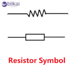
There are two primary resistor symbol standards used worldwide: IEC (International Electrotechnical Commission) and ANSI (American National Standards Institute).
- The IEC resistor symbol is depicted as a simple rectangular box, widely used in European schematics.
- In North American notation, this symbol of an ANSI resistor looks like a zigzag line.
The visual style of both is different, though they can be treated as the same electrical parts, according to local traditions. The knowledge of those variations of symbols is necessary when reading datasheets, creating circuit diagrams, or reading diagrams of foreign origin. The use of a single standard provides test consistency and removes confusion when analyzing the circuit.
Types of Resistor Symbols and Their Meanings
There are many types of resistors, each of which is described by a different symbol in circuit diagrams. Overall, typical categories include those listed in the table below:
|
Type |
Symbol Description |
Function / Use Case |
|
Fixed Resistor |
Zigzag or rectangle |
Limits current, controls voltage |
|
Variable Resistor (Rheostat) |
Arrow across resistor |
Adjustable resistance |
|
Potentiometer |
Three-terminal version |
Voltage divider, control knob |
|
Thermistor |
Resistor with temperature curve line |
Temperature sensing |
|
LDR (Light Dependent Resistor) |
Arrows pointing at resistor |
Light sensing circuits |
|
Fuse Resistor |
Resistor symbol with a fuse mark |
Protection from overcurrent |
The symbols have different electrical behavior. An example of this includes variable resistors, which are manually controlled to vary the circuit resistance, and thermistors and LDRs, which respond automatically to the environment. These differences are also useful in the proper identification of the circuit functions and designing responsive systems.
How to Read and Identify Resistor Symbols in Circuits
Resistor Labeling Conventions
Every resistor symbol includes a reference designator (R1, R2, etc.) and its resistance value, usually in ohms (Ω), kilohms (kΩ), or megohms (MΩ). These labels correspond to specific components on the PCB.
Circuit Context and Configuration
Resistors can be of series type, parallel type or voltage divider type. The identification of these arrangements shows the way in which they regulate the flow of voltage and current.
Reading Complex Circuit Combinations
In high-level circuits, biasing, filtering, or signal balancing networks can be made up of more than two resistors. Exerting the learning of these combinations of symbols enhances the precision in designing and troubleshooting designs.
Circuit Diagram Examples Featuring Resistor Symbols
Series Circuit Example
In a series circuit, resistors are laid across each other, and they make the current pass through them. Voltage is divided in operation with resistance values.
Parallel Circuit Example
In a parallel configuration, resistors share the same voltage but divide current into separate branches, reducing total resistance.
Voltage Divider Example
A voltage divider is constructed by using two or more resistors in order to produce a given output voltage. This schematic is critical in the design of sensors, ADC input and analog control circuits.
Practical Application Insight
These examples show how symbolic representations directly translate to circuit behavior. Recognizing resistor symbols in different contexts enhances comprehension of electronic design.
Understanding Resistor Labels and Notations
Reference Designators and Values
Resistor labels such as “R5 10kΩ” denote both identity and electrical value. They are typically placed near the resistor symbol for clarity.
Power Rating and Tolerance
Every resistor has a power rating (e.g., 0.25W, 1W) and tolerance (±1%, ±5%), defining its performance stability. Understanding these ensures correct component selection for thermal reliability.
Cross-Referencing with BOM and PCB
The ability to label the data properly assists the engineers in aligning the schematic data to the bill of materials (BOM) and physical PCB layout to avoid inputting errors during assembly and to enhance efficiency in maintenance.
Common Mistakes in Reading Resistor Symbols
Misidentifying Variable Components
Beginners often confuse variable resistors and potentiometers since both include arrows. However, potentiometers have three terminals for voltage division.
Misreading Resistance Values
Misunderstanding of units (O, kO, MO) or lack of tolerance may result in circuit mistakes and faults in the design.
Polarity Misconception
Non-polarized components are resistors, which work in the same manner, regardless of orientation. This identification will avoid complicated misunderstandings in the process of assembly or troubleshooting.
Comparison: Resistor Symbol vs. Capacitor & Inductor Symbols
In order to see the symbols of resistors better, it is useful to compare them to the similar symbols of other passive components:
|
Component |
Symbol Shape |
Main Function |
|
Resistor |
Zigzag / Rectangle |
Limits current |
|
Capacitor |
Parallel lines |
Stores electric charge |
|
Inductor |
Coiled line |
Induces magnetic field |
Capacitors and inductors store and release energy respectively, unlike resistors which are used to regulate the current and voltage present. The identification of visual and functional distinctions amongst such symbols is a way of enabling engineers to understand schematics quicker and develop balanced electronics.
Practical Applications of Resistor Symbols in Real Circuits
Connecting Resistor Symbols to Real-World Circuit Functions
Circuit diagram symbols Resistors symbolically used in circuit diagrams to represent circuit concepts into actual situations. Each of the resistor symbols is a physical device that has an effect on the behavior of voltages and currents and power in an electrical system. The knowledge of these symbols can enable engineers and technicians to anticipate the behavior of the circuit prior to the construction of the hardware or in troubleshooting the hardware.
Current Limiting and LED Protection
One of the most common practical uses of resistor symbols is in LED circuits. The resistor symbol placed in series with an LED represents a current-limiting resistor. This element makes sure that the current flowing through the LED is only a safe amount and thus the LED does not overheat or burn out. The symbol of resistor would in this instance indicate a critical protective purpose in low-voltage lighting and indicator circuits.
Voltage Division and Signal Conditioning
Voltage divider circuits often use the symbol of a resistor in analog or digital electronics. Input voltage is split into smaller and controlled outputs by a combination of two or more resistors that are connected in series. Engineers apply these configurations to power microcontrollers, sensors, or operational amplifiers with reference voltages. By understanding these symbols of resistors within the schematics, it is possible to learn about signal-scaling functions that are needed to make the correct readings and ensure the control is stable.
Biasing and Sensor Networks
Resistor symbols also define biasing networks in transistor or op-amp circuits, determining proper operating points for amplification. Specialized symbols of resistors (temperature-dependent, such as thermistors), and light-sensitive (LDR) are used in sensor systems to indicate an element of environmental sensing. The resistors transform measurable electrical variations to physical conditions, which are the foundation of automation, IoT, and environmental monitoring applications.
FAQ
What’s the main difference between IEC and ANSI resistor symbols?
The IEC standard takes the shape of a rectangular box, unlike ANSI that takes the form of a zigzag line. The two represent the same role.
How can I identify a variable resistor in a schematic?
Look for a diagonal arrow crossing the resistor symbol—it indicates adjustable resistance.
Are resistors polarized components?
No, resistors are not three-dimensional, i.e., you can have them any which way when fitting.
Do resistor symbols differ in AC and DC circuits?
No, the symbol is the same, but the current flow and the circuit behavior are different depending upon the type of signal.
Why is understanding resistor symbols important?
It will provide proper circuit design, minimize troubleshooting time, and enhance communication between technicians and engineers.
Conclusion
Resistor symbols are a basic knowledge that one requires when working with electronics. The schematic notations offer a remarkable and standardized way of representing resistance on any kind of circuit. To not only understand how to design and troubleshoot circuits, but also enhance communication between engineers around the world, learning how to read and interpret resistor symbols is important. With the ever-evolving types of resistors, the symbolic representation is one of the universal foundations of electronic circuit design.
Some images are sourced online. Please contact us for removal if any copyright concerns arise.


