


What is a Shunt Resistor and How Does It Work?
Understanding Shunt Resistors
Shunt resistors are precise low-resistance devices meant for measuring current incrementally in a circuit. Under the operation of Ohm's Law, the shunt resistor allows a small controlled portion of flow to itself while supplying the largest flow through the main circuit, generating a voltage drop across the shunt resistor that is exactly proportional to the flow that passed through.
Key Components and Structure of Shunt Resistors
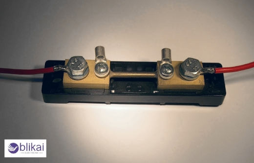
The resistive element of the shunt resistance is mostly manganin or zeranin alloy and two terminals of a sufficient magnitude for connection. The resistive element will have a very low resistance of almost a milliohm or microsnman; this is to assure power dissipation and voltage drops in the lowest form. In most cases of shunt resistors, one may find use of the four-terminal Kelvin connection where one can take accurate measurement because of the separate current and sense voltage paths.
Types of Shunt Resistors
Ammeter shunts: Used in analog ammeters to extend their current measurement range.
DC shunts: Designed for high-current DC applications.
AC shunts: Optimized for accurate measurements in AC circuits.
Panel-mount shunts: Integrated into electrical panels for easy current monitoring.
PCB-mount shunts: Small, surface-mount devices for use in printed circuit boards.
How Shunt Resistors Work
Principles of operation
Shunt resistors operate on an extremely simple principle: they are placed in parallel with the circuit under measurement so that a small part of the current flows through them. This "shunting" of current is the key to their functionality.
Ohm's law and current measurement
The operation of shunt resistors is instantly clear from an important law called Ohm's law. In simple terms, if the value of the resistance is known, the value of the current flowing through the shunt can be calculated from the voltage drop across it. The relationship is basic as: I equals V over R, where I is the number of amperes, V is the voltage, and R is the resistance.
Voltage drop across the resistor
When current flows through a shunt resistor, there is a smaller voltage drop created. This voltage drop is directly proportional to the current circuit. Measurement of this voltage drop gives current in the main circuit without causing blockage to its operation.
Amplification of small signals
In many practical cases, there is a very small voltage drop across the resistor. In order to obtain a useful detection signal, it is necessary to amplify this signal in one form or another. This amplification allows for more accurate readings and integration with other measurement and control systems.
Applications of Shunt Resistors
Current Sensing in Electrical Circuits
Shunt resistors are the best for measuring current, which flows in various electrical circuits. An engineering practice of putting a low-resistance shunt in series with the circuit allows accurate current measurements using the voltage drop across the resistor. This application would typically control and monitor the current in power supplies, industrial systems, and automotive applications.
Battery Management Systems
Shunt resistors are the linchpins in battery management systems for charge and discharge rate monitoring. They protect against overcharging and over-discharging of the battery, thus increasing the duration of battery life and ensuring safe operation. This application holds more significance in electric vehicles, renewable energy storage systems, and portable electronic devices.
Motor Control and Protection
Shunt resistors are essential components in motor control circuits. They provide accurate current feedback, enabling precise speed control and torque management. Additionally, they protect motors from overcurrent conditions by triggering protective measures when excessive current is detected.
Power Distribution Monitoring
In power distribution networks, shunt resistors are used to monitor current flow at various points. This application helps utilities and industrial facilities manage load balancing, detect faults, and optimize energy consumption. Shunt resistors in this context often need to handle high currents and maintain accuracy over extended periods.
Overcurrent Protection
Shunt resistors serve as critical components in overcurrent protection systems. By continuously analyzing the current live, they cause the circuit breaker or any other overcurrent protective devices to operate, thus preventing equipment damage and ensuring safety in electric power systems.
Advantages of Using Shunt Resistors
High accuracy in current measurement
Shunt resistors offer exceptional precision in measuring electrical current, making them indispensable in various applications. Their low resistance and tight tolerances ensure minimal impact on the circuit while providing highly accurate readings. This accuracy is crucial in sensitive equipment and high-precision industrial processes.
Cost-Effectiveness
One edge that shunt resistors have over some other options is the cost factor. Compared to devices for more complex current measurements, shunt resistors are one way cheaper to manufacture and apply. Given this particular factor, such devices are mushrooming in both industrial applications and desktop electronic projects.
Simplicity and Reliability
Shunt resistors are known for their simplicity in design and operation. With no moving parts or complex circuitry, they are inherently reliable and less prone to failure. This simplicity also translates to easier maintenance and longer operational lifespans, reducing downtime and replacement costs in various applications.
Wide range of current handling capabilities
Shunt resistors are versatile current sensors capable of measurement in various ranges from milliamps to thousands of amperes, making them applicable in many situations. This versatility tends to increase their use by engineers in a vast range of settings, from small electronic devices to large power distribution systems.
Selecting the Right Shunt Resistor
A. Determining the required resistance value
The first step is to determine the value of resistance for any shunt resistor. The value depends on the maximum current to be found and the maximum permissible voltage across the resistor. Low resistance values allow higher current measurements to be made, with smaller voltage drops, thus probably making for somewhat more difficult measurements to be made accurately.
B. Power rating considerations
The power rating of a shunt resistor determines how much heating it can tolerate from the current flowing through it. The maximum power dissipation can be calculated using the relationship P = I ^2 R, where I is the maximum current detected and R is the resistance value. Choose a shunt resistor of power rating greater than the dissipated power calculated so as to allow for safe operation and to preclude overheating.
C. Temperature coefficient of resistance
The temperature coefficient of resistance (TCR) indicates how much the resistance varies with temperature. A low TCR helps to reduce the error in measurements due to changing temperature; thus, for high accuracy, a shunt resistor with a very low TCR should be chosen. Manganin and Zeranin alloys are popular choices for their low TCR properties.
D. Physical size and mounting options
Consider the available space in your circuit and the mounting requirements when selecting a shunt resistor. Larger resistors can typically handle higher power dissipation but may not fit in compact designs. Choose a resistor with appropriate terminals or mounting options that suit your PCB layout and assembly process.
Installation and Best Practices
Proper placement in circuits
When installing shunt resistors, proper placement is crucial for accurate measurements. To minimize voltage drops across the conductors, place the shunt resistor as close to the load being measured as practically possible. Ensure that the shunt is connected in series with the path through which you want to measure current-usually on the low-side(ground) of the circuit.
Minimizing thermal effects
To minimize thermal effects, consider the power dissipation of the shunt resistor. Select a resistor that has an adequate power rating, and radiate heat away from it where necessary. Mount the shunt resistor away from heat-sensitive components and ensure proper airflow around it to maintain consistent performance.
Kelvin connections for improved accuracy
Implement Kelvin connections to improve measurement accuracy. This four-wire connection technique separates the current-carrying path from the voltage sensing path, thus, nullifying the effects of lead and contact resistance. Achieve accurate readings by placing the voltage sensing leads as close as possible to the body of the shunt resistor.
Shielding and noise reduction techniques
To reduce electromagnetic interference and improve measurement accuracy, employ proper shielding techniques. Use shielded cables for voltage-sensing connections and ground the shield at one end only to prevent ground loops. Consider using twisted-pair wiring for differential voltage measurements to further reduce noise pickup.
Conclusion
Shunt resistors are an important component in electrical and electronic systems and provide a quick, simple, and cost-effective way of measuring current. Understanding their working principle, types of applications and advantages will assist engineers and technicians in choosing and deploying these components in their own designs.
Proper selection and installation of shunt resistors ensure effective functioning and accurate measurement of current with optimal performance of systems. Such aspects included power rating, temperature coefficient, and resistance value among others. Through adherence and compliance with proper industrial practices during installation and maintenance, the durability and reliability of these elements are maximized to the benefit of any electrical application.
Related Articles
What is a Variable Resistor & How Does it Work?
What is a Neutral Earthing Resistor? [Explained]
Chip Resistor: characteristics, Applications & Advantages
Decoding Resistor Color Bands: A Beginner's Guide
Ballast Resistors: Operation, Applications, and Optimization
Resistor Transistor Logic (RTL): Operation, Variations, Traits & Uses


