


How to Test a PNP Transistor
What are PNP Transistors?
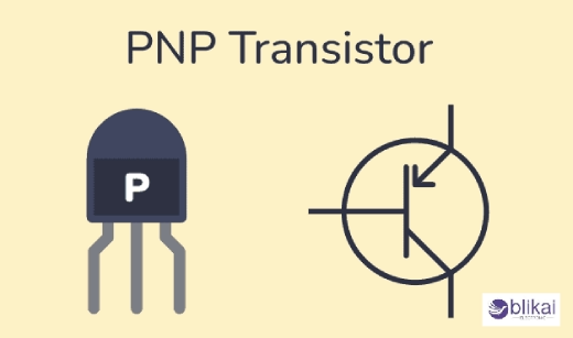
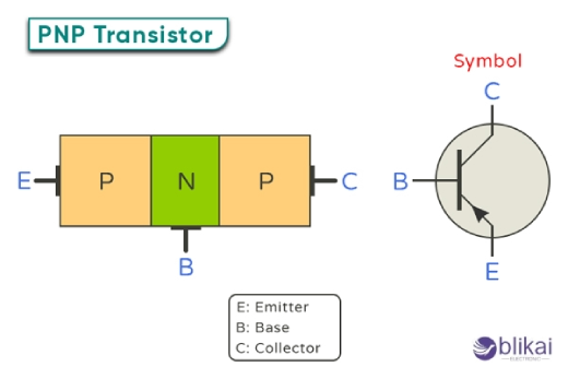
PNP transistors are one of the basic semiconductor building blocks in electronics. These types consist of three layers: P-type emitter, N-type base, and P-type collector. "PNP" is the name given to these devices because of their sequence. In them, current flow is controlled by the movement of holes with a positive charge through the semiconductor.
The emitter injects holes into the base region while the collector attracts them to the collector. The thin base layer acts as a control mechanism, regulating the flow of holes between the emitter and collector. This unique structure allows PNP transistors to amplify signals or function as switches in electronic circuits.
Applications of PNP Transistors
Amplification circuits
PNP transistors are key devices in amplification circuits, particularly in audio applications. They are mainly used to increase the various amplified signals that produce high sound through the preamplifiers of microphones and amplifiers for electric guitars. This PNP transistor takes advantage of its characteristics to reproduce a high-quality sound virtually distortion-freely.
Switching applications
PNP transistors excel in switching applications. They are commonly used in logic circuits and digital systems where rapid on-off switching is required. PNP transistors can effectively control larger currents with smaller input signals, making them valuable in relay drivers and motor control circuits.
Current sources
PNP transistors are excellent for creating stable current sources. This capability is instrumental in analog circuits where consistent current flow is crucial. Applications include LED drivers, where PNP transistors can maintain a steady current to ensure uniform brightness across multiple LEDs.
Level shifting
In mixed-voltage systems, PNP transistors are invaluable for level shifting. They can translate signals between different voltage levels, allowing communication between components operating at various voltages. This function is essential in modern electronic designs with standard power rails.
Selecting the Right PNP Transistor
Key parameters to consider
Some parameters must be considered when selecting the proper PNP transistor for any application. To start, think about the maximum collector current IC and maximum collector-emitter voltage VCEO ratings to determine the transistor's power handling capacity. The current gain hF is also very significant because it informs us how many times the transistor can amplify the base current. Consider switching speed, which is essential for high-frequency applications, as shown by rise and fall time parameters.
Common PNP transistor models
Common PNP Transistor Models-Several popular PNP transistor models are used in many types of electronic circuits. 2N3906 is a general-purpose small-signal transistor that finds use in low-power applications. For higher power requirements, the TIP32 series is commonly employed. The BC557 is another versatile option for small-signal amplification and switching applications. These models offer different specifications and are chosen based on the specific needs of the circuit design.
Reading datasheets effectively
One should learn how to read datasheets effectively to make an informed decision when choosing a PNP transistor. The most outstanding indicators are those absolute maximum ratings that show the transistor will meet the requirements of your circuit. With extreme attention, look at the electrical characteristics table containing typical and maximum values for the different parameters. The graphs and charts in the datasheet are valuable because they provide a good overview of how the transistor works in various conditions. By recognizing these features, this information will allow you to select the most appropriate PNP transistor for your application.
Preparing for the Test
Necessary tools and equipment
Testing a PNP transistor can be done with a few simple tools. TheThe most important item is a digital multimeter that measures resistance and continuity. Perform a battery check to ensure the device is working properly. You may also need a pair of needle-nose pliers or tweezers to handle small components safely. A magnifying glass can help identify pin markings on smaller transistors.
Safety precautions
The first thing to take into account is safety. The workspace should be clean and dry before any work is done, and you shouldn't touch the transistor's leads with bare hands; otherwise, this causes static discharge. If testing a lift-out transistor, ensure it is switched off completely. Use proper eye safety measures, as anything could happen, and you could be subject to sparks or debris.
Identifying transistor pins
Most importantly, the pins of PNP transistors are structured precisely: emitter, base, and collector. If they are not correctly identified, the testing and ultimate reading will not be correct. Most transistors have a flat side or a tiny tab found at the emitter pin. Look for each pin configuration on the appropriate manufacturer's data sheet; it does differ between manufacturers and even specs. If the transistor is in the circuit, follow the connections and proceed to ask what the pin does, one by one.
Visual Inspection
Checking for physical damage
Before any further electrical tests, it is wise to visually inspect the PNP transistor for visible signs of damage, cracks, burns, or discoloration on the body. Similarly, take note of the leads: They should be relatively straight with no corrosion. Any physical abnormalities can indicate potential issues with the transistor's functionality.
Identifying manufacturer markings
Most PNP transistors have specific markings that provide valuable information. Look for a series of letters and numbers on the transistor's body. These markings typically include the manufacturer's code, transistor type, and sometimes performance characteristics. Familiarize yourself with common marking schemes to interpret this information accurately.
Verifying transistor type
Confirming that you indeed have a PNP transistor is essential. PNP transistors often have prefixes like "2S" or "2SA" in their part number. Additionally, check the datasheet corresponding to the transistor's markings to verify its type and specific characteristics. This step ensures you're working with the correct component and helps prevent potential mistakes in subsequent testing procedures.
Using a Multimeter for Testing
Setting up the multimeter
Before testing a PNP transistor, it is crucial to set up your multimeter correctly. Start by selecting the diode or resistance mode on your multimeter. Be sure that both the red and black examinations are plugged into their separate jacks, the red probe into the VOhm port and the black probe into the COM port. The multimeter is now set to its smallest resistance range, allowing for precise readings.
Testing base-emitter junction
To test the base-emitter junction, connect the red probe to the emitter and the black probe to the base. A working PNP transistor should register a low resistance reading( from 0.45 V to 0.70 V). Reverse the probes; you should see an open circuit or very high resistance.
Testing base-collector junction
Next, connect the red probe to the collector and the black probe to the base to examine the base-collector junction. Again, a working PNP transistor should show a low resistance reading in this configuration. You should see an open circuit or very high resistance when you reverse the probes.
Interpreting multimeter readings
A functional PNP transistor will show low resistance (or voltage drop in diode mode) when the emitter and collector are favorable relative to the base. If you observe low resistance in both directions or high resistance in both directions for either junction, the transistor is likely faulty. Remember that slight variations in readings are normal, but significant deviations indicate a problem.
Troubleshooting Common Issues
Identifying short circuits
A short circuit with PNP transistors could damage the device and affect the circuit's operation. You can test for short normally using a multimeter by taking either continuity testing mode or resistance mode. Test between the collector and emitter terminals. A reading of zero or very low resistance indicates a short circuit. Also, check between the base and emitter and base and collector. Any unexpected low resistance readings between these terminals suggest a short circuit.
Detecting open circuits
An open circuit occurs if there is an interruption in the internal connections of the transistor. Set your multimeter to the diode test mode to detect an open circuit. Place the red probe on the base and the black probe on the emitter. You should see a forward voltage drop (typically 0.6-0.7V). Repeat this test with the red probe on the base and the black probe on the collector. You likely have an open circuit if either test shows no reading or "OL" (overload).
Addressing leakage problems
Leakage problems in PNP transistors may cause unwanted current flow, affecting the circuit's performance. For leakage testing, use a multimeter with the highest resistance setting. Connect the positive lead to the emitter and harmful to the collector. A suitable PNP transistor should show very high resistance or "OL." If you get a lower resistance reading, it indicates leakage—similarly, test between the base-collector and base-emitter. Any unexpected low resistance readings in these tests suggest leakage issues that need addressing.
Conclusion
Testing PNP transistors is a life-bearing test that every electronics enthusiast and professional should have. Good testing not only aids in identifying faulty components but also ensures the reliability of electronic projects. Testing PNP transistors, whether for basic trouble-fixing or advanced refining techniques, surely elevates one's expertise level in electronics.
Related Articles
Resistor Transistor Logic (RTL): Operation, Variations, Traits & Uses
Tip41c: What Makes It a Reliable Power Transistor?


