


5V Relay Pinout: Working & Its Applications
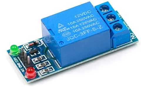
Switching is performed by electro-mechanical components called relays. For contact switches to open or close, the coil of the relay is energized by DC. There are two normal contacts (NO) and a coil in a 5V relay module with one channel. It is the goal of this article to give you a better understanding of how a 5V relay module works. A relay module's pin arrangement and its function must be understood first before getting into the details.
What is a 5V Relay Module?
Electronic relay modules use low-power signals to control high-power devices. The term relay refers to an electrically operated switch. Relay coils typically react to voltages much lower than those used to switch the connected devices, so 5V refers to the voltage required to activate the coil. Relay contacts are energized when the coil receives 5 volts and connects or disconnects the circuit.
There are numerous applications for these relay modules, including home automation, industrial control systems, and robotics. Lights, fans, and other appliances can be controlled remotely using these devices in smart homes. It ensures safety and reliability by separating the load circuit from the control circuit (low voltage). A galvanic isolation circuit is also necessary for protecting sensitive components from spikes or noise in the circuit. 5V relay modules are vital components in electronic projects that control high-power devices using low-power signals.
How Does A Relay Work?
Controlling a circuit via relays is achieved by using electromechanical switches. The components of these systems include:
Coil: Wires are usually wound around a core of copper wire in relay coils. A magnetic field is generated by an electric current passing through a coil.
Contacts: An actual switch element consists of one or more sets of contacts. In the case of a changeover contact, it can be either normally open (NO), normally closed (NC), or a changeover contact (CO). NC contacts are closed by default, while NO contacts are open.
Armature: Contacts are connected to the armature, which is a movable component. Magnetic fields generated by energized coils attract the armature, which causes it to move.
In detail, here's how relays work:
De-energized State (Normally Closed Contacts): Magnetic fields around coils are minimal when no current flows through them. Spring-driven contacts of the relay are mechanically connected to the relay's common terminal in this state. These terminals are connected to a circuit that flows electricity.
Energizing the Coil: Induction coils generate magnetic fields when current is applied. Current flowing through the coil determines the strength of this field. Magnetic fields attract armatures towards coils as they build up.
Changing State (Switching Contacts): During the movement of the armature towards the coil, the contacts are mechanically separated. An armature moving opens normally closed relay contacts. Conversely, its contacts close when its armature moves if their contacts are normally open. Relays are effectively changed from their default state by this action.
Maintaining State: As long as the current through the coil is sufficient to maintain the magnetic field, once the relay is energized and the contacts have switched, it typically remains in that state.
De-energizing the Coil: Once the current through the coil is turned off, the magnetic field collapses, giving rise to the release of the armature. Normal open contacts close the circuit when the relay returns to its default position. In contrast, a normally closed contact returns to the default setting, allowing the circuit to be closed.
5V Relay Pin Configuration
A typical 5V relay module has several pins, each serving a specific function. Here's a common pin configuration for a 5V relay module:
VCC: Power is supplied to the relay module through this pin. "5V" refers to the power requirement of a DC power supply that is typically 5V DC. Power supplies usually connect this pin to their positive terminals.
GND: Ground pins provide the relay module with a reference voltage. In the controlling circuit, it is connected to the ground or the negative terminal of the power supply.
IN: This pin is used for controlling the device. When this pin is connected to a logic HIGH (5V) signal, the relay is activated, whereas when it is connected to a logic LOW (0V), it is deactivated. An electronic device that can produce a digital signal, such as a microcontroller or sensor, can provide the control signal.
NO (Normally Open): The relay's switch terminals are located on this pin. This pin is disconnected from the COM (Common) pin by default (when the relay is not energized). NO and COM become connected when the relay is activated.
COM (Common): A common pin connects to the control device at one end (the load). When switching configurations are desired, either the NO or NC pin is used.
NC (Normally Closed): A relay's other switch terminal is located on this pin. COM is the pin it connects to when installed. NC and COM are disconnected when the relay is energized.
Features
Several applications call for the use of 5V relay modules - which are versatile electronic components used to control high-power devices with low-power signals. We'll take a closer look at its features:
Voltage Rating: 5V relay modules are controlled by a 5 volt DC voltage, as their name suggests. Microcontrollers and sensor modules typically supply this voltage, such as digital output pins on a microcontroller.
Switching Capacity: Relay modules have a switching capacity based on the maximum voltage and current they can handle. There are a variety of relay modules available with varying volts and amps.
Contact Configuration: The contact configurations of relay modules can be either normally open (NO), normally closed (NC), or changeover (CO). Relays can be wired into circuits in a variety of ways based on the application's requirements.
Coil Current: For the relay coil to activate and the switch contacts to be activated, a coil current is needed. Coils in relay modules operate at low currents, typically tens of milliamps in the case of 5V modules.
Response Time: When a relay receives a control signal, it takes a certain amount of time to switch its contacts. Time-critical applications need to consider relay response times even though they are generally fast (typically, they are in the millisecond range).
Isolation: The control circuit and load circuit are often galvanically isolated by relay modules. By preventing voltage spikes or noise from affecting the load circuit, sensitive control circuitry is protected.
LED Indicators: Relay modules often have LEDs built-in to indicate whether or not they are operating. As soon as the relay is powered up, these LEDs illuminate, giving the user visual feedback.
Mounting Options: Different types of relay modules are available, such as PCB-mounted, DIN rail-mounted, and socket-mounted models. The system is easy to integrate with a variety of electronic enclosures and systems.
Operating Temperature Range: There is a specified temperature range within which relay modules can operate. To ensure reliable operation, the relay module's operating temperature range must match the application's environmental conditions.
Durability: During the course of their operation, relay modules can be switched repeatedly. Commercial and industrial applications benefit from the robust construction of high-quality relay modules.
How to Use/Relay Module Circuit Diagram
A single-channel relay module's circuit can be seen in the diagram below. This circuit illustrates how a digital signal activates and deactivates the relay module. Relay modules receive this signal on their control pins. The diagram below shows how an internal 5V single-channel relay module is constructed.
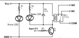
A single channel relay module is shown in the circuit diagram above, which contains 2 resistors, 2 transistors, 2 LEDs & 1 5V relay. Depending on the type of control signal used to activate the relay, relay modules can be classified into two types. The NPN transistor is found in one relay module, while the PNP transistor is found in another. The control pin of an NPN transistor will be active high in order to activate a relay module using an NPN transistor. As an alternative, if a PNP is used, then an active low signal will be sent to the control pin to activate the relay.
By connecting a NO pin to COM, the coil in a relay module activates when a high signal is applied to the control pin. We can also deactivate a relay using a freewheeling diode once we provide an active low no signal to its control pin.
For PNP-based relay modules, a low active signal activates the relay, while a high active signal deactivates it. It is possible to connect any microcontroller to a 5v single channel relay module and control it. The control pin is controlled with a GPIO pin, which is similar to a digital o/p pin. There is an audible sound when the relay is activated.
Wrapping Up
The 5V relay is one of the most important components in electronics, as it acts as a bridge between devices with low-power controls and devices with high-power controls. Home automation, industrial control systems, and robotics all use its versatility, ease of use, and reliability. Featuring galvanic isolation, multiple contact configurations, and LED indicators, the 5V relay provides robust performance and flexibility.
For effective integration into electronic circuits and safe and efficient operation, it is important to understand the pinout and features of the 5V relay. 5V relays are designed to switch high-power loads with low-power signals and can be used for lighting, motors, heaters, and other electrical appliances. Modern electronics rely on 5V relays to control and automate virtually all kinds of applications across a wide range of industries.


