


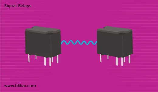
What is Signal Relays? Everything You Need to Know
A signal relay is an electrical element that's used to supply a circuit with low- power control signals. Electrical isolation exists between the output and the controls. Here are the key points about signal relays:
Types of Signal Relays
- Electromechanical Relays (EMR): Opens and closes a circuit using a physically moving component, such as armor.
- Solid State Relays (SSR): Uses switchable electrical components that don't have any moving parts.
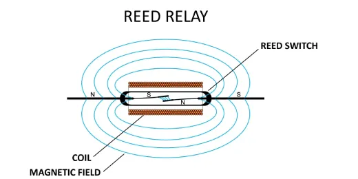
- Reed Relays: Makes use of two electromagnetic reeds that are affected by a magnetic field to open and close.
Components of a signal relay
Electromechanical Relay Components:
1. Electromagnet (Coil)
- Core: Usually composed of steel. When an electric current overflows through the coil, it turns glamorous .
- Coil: A wire coiled around a core that, when current passes through it, produces a magnetic field.
2. Armature
- A magnetically-based moveable arm or pad. When power is applied to the coil, it is drawn in by the electromagnet.
- Mechanically linked to contacts on the relay. Induce it to open or shut.
3. Spring
- Enables the coil to be de-energized and returns the armature to its initial position. to guarantee the recovery of the contact to its original state.
4. Contacts
- Common (COM): The terminal that is always connected to the moving part of the switch.
- Normally Closed (NC): When the relay coil is not powered, the contact is connected to the common contact.
- Normally Open (NO): When the relay coil is powered on, the contact is linked to the common contact.
- These contacts switch between open and closed states to control the circuit.
5. Frame
- The framework that binds every element together. Encourage and safeguard the mechanism.
6. Yoke
- The section of the magnetic circuit in charge of managing the magnetic flux between the armature and core.
Solid-State Relay Components:
1. Input Circuit
-Optocoupler (Optoisolator): In one box, a light detector and an LED. offers separation of the input and output electrically.
-Control Circuit: The circuit that interprets the input signal and turns on the optocoupler's LED.
2. Trigger Circuit
-Converts the signal from the optocoupler into a signal suitable for driving the output switch.
3. Output Circuit
-Thyristor, Triac, or MOSFET: A semiconductor device with switch functionality. Turn the load on or off based on the signal received from the input.
-Snubber Circuit: Shields semiconductors from changes in voltage.
4. Heat Sink
-To avoid overheating, it distributes the heat produced by semiconductor components.
5. Protection Components
-It might have parts that guard against overvoltage, overcurrent, and short circuit, including varistors, diodes, or fuses.
How signal relays work
Low-power control signals are used by signal relays, which operate on electromagnetic principles to regulate the flow of electric current in a circuit. A detailed description of how signal relays operate may be found below:
Electromechanical Signal Relays:
1. Electromagnet and Armature Interaction:
-Electromagnet (Coil): An iron core is encircled by a coil inside the relay. A magnetic field is produced around the core of this coil when electric current flows through it.
-Armature: It is linked to the relay's internal moving components. Usually, ferromagnetic materials—like steel or iron—are used to make them. The armature is drawn to the electromagnet when the coils get energized by the magnetic force generated.
2. Contact Mechanism:
-Normally Open (NO) Contact: The relay connections are open in the initial condition, which occurs when the coil is de-energized. This indicates that the terminals attached to the NO contacts are not electrically connected.
-Normally Closed (NC) Contact: In contrast, the NC contacts are closed in the initial condition to provide a constant electrical connection between the terminals.
3. Energizing the Relay:
-When the strength of the control signal is low, it is sent into the relay coil (typically from a switch, sensor or electronic circuit). A magnetic field is produced around the core by it.
-The armature is drawn toward the electromagnet by this magnetic field. Its status can be altered by relocating individuals.
4. Switching Action:
-NO Contact Closure: Energizing the relay causes the armature to move, closing the normally open contacts. This completes the circuit between the terminals connected to the NO contacts, allowing current to flow through the load connected to the relay.
-NC Contact Opening: Simultaneously, the normally closed contacts open as the armature moves, interrupting any current flow through the NC circuit.
5. Maintaining State:
-The magnetic field surrounding the core collapses when the control signal is cut off (coil de-energised).
-The armature is brought back to its initial position by the retraction spring that is attached to it. and put the contacts back to how they were.
-The relay remains in this state until another control signal is applied.
Solid-State Relays (SSRs):
In discrepancy to electromechanical relays, SSRs serve else. SSRs use semiconductor switching devices(similar thyristors or MOSFETs) to regulate the inflow of electric current rather than mechanical and electromagnetic connections.
1. Optical Isolation:
- An optocoupler, or light detector, and an LED are common components of an SSR's input circuitry.
- The LED illuminates and emits light in response to an applied control signal, activating the light detector.
2. Solid-State Switching:
- A MOSFET or thyristor, or semiconductor switching device, is activated in the SSR's output circuit by the light detector.
- When a control signal is applied, it permits current to pass through the SSR; when the signal is removed, it prevents current inflow.
Key Features of Signal Relays
1. Isolation
-Electrical Isolation: Make that high-power circuits are electrically isolated from the control circuit. shields delicate components and stops interference.
-Optical Isolation (in SSRs): In order to create isolation between input and output, optocouplers are utilized. It enhances noise immunity and safety.
2. Switching Capacity
-Voltage and Current Ratings: Relays for signals are rated for particular voltage and current levels. to make sure it can sustain the weight for which it was intended.
-Breaking Capacity: The maximum current the relay contacts can safely interrupt without damage.
3. Types of Contacts
-Normally Open (NO): When the relay is turned on, the connections are closed, and when it's turned off, they're open.
-Normally Closed (NC): When the relay is turned on, the connections are open, and when it's turned off, they're unrestricted.
-Form Types: DPST(Double Pole Single Throw), DPDT(Double Pole Double Throw), SPDT(Single Pole Double Throw), and SPST(Single Pole Throw) are exemplifications of common combinations.
4. Response Time
-Operate Time: The duration needed by the relay to transition from ade-energized to an reenergized condition.
-Release Time: The quantum of time it takes for the relay tode-energize itself once the control signal is cut off.
-Fast Switching: Relays that are solid state generally respond briskly than those that are electromechanical.
5. Durability and Life Cycle
-Mechanical Life: The number of operations the relay can perform before mechanical failure, typically measured in cycles.
-Electrical Life: The number of operations the relay can perform before electrical failure, influenced by the load and switching conditions.
6. Temperature and Environmental Resistance
-Operating Temperature Range: The range of temperatures at which the relay can serve dependably.
-Environmental Protection: Characteristics like a closed shell. To guard against dust, moisture, and other contamination, standardized coating and IP (Ingress Protection) rating are used.
7. Control Voltage
-Coil Voltage Range: The range of voltages that can be used to supply it to the relay coil For illustration, 5V, 12V, 24V,etc.
-Coil Power Consumption: How much power the relay coil uses when it is turned on.
8. Size and Mounting
-Form Factor: A range of dimensions, from big panel mount units to tiny PCB mount relays.
-Mounting Options: Through-hole installation is one of the options. DIN rail mounting and surface installation for simple system integration.
9. Safety and Compliance
-Standards Compliance: Conformity to assiduity norms, including CE( Conformité Européenne), IEC( International Electrotechnical Commission), and UL( Underwriters Laboratories).
-Safety Features: Built-in defense mechanisms, such arc suppression. both surge and thermal protection.
10. Additional Features
-Status Indicators: The LED lights up to show whether the relay is powered on or off.
-Feedback Mechanism: Certain relays are equipped with sensors or feedback contacts to track performance and status.
-Interlocking and Redundancy: Features to prevent simultaneous activation of multiple relays, enhancing system reliability.
Advantages
- Isolation: High electrical isolation between input and output.
- Control: Ability to control high power circuits with low power signals.
- Reliability: Long operational life, especially in SSRs with no moving parts.
Disadvantages
- Size: Physical relays can be bulky.
- Speed: Comparatively speaking, switching semiconductors is faster than electromechanical relays.
- Wear and Tear: An EMR's moving components may deteriorate with time.
Applications
- Automotive: Controlling lights, fans, and other accessories.
- Industrial Automation: Switching motors, valves, and other equipment.
- Telecommunications: Communication network circuits for signal routing and control.
- Consumer Electronics: Control over HVAC systems, appliances, etc.
Selection Criteria
- Load Requirements: Voltage, current, and kind of load (capacitor, inductive, or resistive).
- Control Signal: Regulate the voltage and current of the signal.
- Environmental Conditions: Humidity, temperature, and potential exposure to unfavorable circumstances.
- Regulatory Standards: Conformity with certification requirements and industry norms.
Considerations
- Switching Speed: Typically slower than solid-state relays due to mechanical movement.
- Lifetime: Mechanical parts may wear out over time, requiring maintenance or replacement.
- Size: Generally larger than solid-state relays.
Related Articles
FIR Filters:Overview,Structure and Signal Processing


