


Load Break Switch : Principle and Its Applications
Electrical distribution systems and operational circumstances necessitate regular synchronization between the power supply and the connected loads. This synchronization can present a notable obstacle and may escalate into a significant safety issue, particularly during the integration or removal of substantial motor loads within the system. Employing a device known as a Load Break Switch can mitigate such issues. In this piece, we shall delve into the concept of load breaking, its operational mechanics, and its practical applications.
What constitutes a Load Break Switch?
A load break switch is a mechanism designed to interrupt electrical current flow within an electric apparatus or circuit when the current surpasses its rated value. Activation is triggered by the magnetic field within the primary power system, and re-engagement occurs upon a decrease in electrical demand, thereby mitigating current surges in circuits with low impedance. These switches boast simplicity in both utilization and assembly, finding utility across diverse domains including public distribution, industrial settings, distribution panels, motor feeders, and emergency shutdowns.
Below is the symbol representing a load break switch.

LBS Symbol
Composition of load break switch
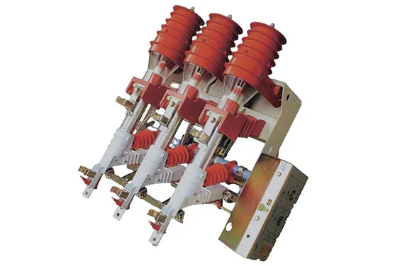
Load break switches primarily consist of sheet steel enclosures, offering straightforward and robust construction. They incorporate epoxy insulators, lagging pins, double switch blades, forged contacts with seamless current paths, and arc quenching chambers. The insulation renders these switches lightweight yet endowed with high mechanical strength and enhanced electrical safety. Available panel configurations include standing Indoor/Outdoor and RMU types. Thus, this piece provides a comprehensive overview of load break switches, covering their functionality and diverse applications.
Load Break Switch Operation Principle
The operational essence of load break switches lies in mechanically manipulating their contacts to establish or interrupt current flow at an appropriate pace. During this process, these switches endure various stresses, including thermal, dielectric, and mechanical forces. Their function extends to safeguarding transformers, presenting an alternative to the conventional two-pole structure.
Features of load break switch
The load break switch boasts several noteworthy attributes:
Exceptional arc-extinguishing capabilities.
Compact and lightweight design.
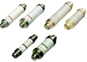
Incorporation of high current-limiting power fuses.
Economical in nature.
Safe and straightforward fuse replacement procedure.
Equipped with a shunt trip mechanism.
Features an indicator for blown fuses.
Includes auxiliary contacts.
Variants available with motor-driven functionality.
Load Break Switch Design
The design of the SF6 gas insulated load break switch predominantly comprises two circuits: the main circuit and the earthing circuit, both enclosed within a dielectric casing constructed from epoxy resin. This dielectric casing excels in resisting contamination and offers exceptional insulating performance. Comprising lower and upper insulating covers, the dielectric casing forms a crucial component of the load break switch assembly.
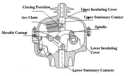
Design of Load Break Switch
Within this dielectric chamber resides SF6 gas maintained at a relative pressure of 0.4 bar. The lower insulating cover features a thinner wall, a precautionary measure to prevent potential explosions. In the event of an accident, excess gas pressure can be safely released through an explosion-proof channel, redirecting it to the rear of the cabinet and alleviating pressure buildup to ensure personal safety.
The design of the SF6 load switch involves the integration of various components. These parts encompass the closing position, isolated position, earthing position, upper insulating cover, upper stationary contact, spindle, M ring, lower insulating cover, sensor, lower stationary contact, air chute, movable contact, ground coupler, and ground contact.
Closing Position:
In the SF6 Load Break Switch (LBS), the closing action involves the contacts being enveloped by SF6 gas at a pressure of 2.8 kg/cm2. When the switch is activated, the moving contact is drawn apart, initiating an arc between the contacts.
Movable Contact:
The movable contact within this switch is responsible for modulating the current flow by mechanically maneuvering its contacts at an appropriate speed to either open or close the circuit.
Upper and Lower Stationary Contacts:
Stationary contacts within the switch serve as the points where the LBS actuation triggers the circuit to be made or broken. Always paired, these contacts remain fixed, with the contact connected to the switch actuator being termed as the stationary contact.
Upper and Lower Insulating Cover:
The insulating cover serves as a protective layer surrounding the Load Break Switch (LBS), enhancing its safety by insulating it from external elements.
Arc Chute:
The arc chute consists of a series of metal plates arranged in parallel, insulated from each other. These plates facilitate the cooling, diversion, and safe suppression of electric arcs. Also referred to as arc dividers or splitters, they effectively dissipate arc energy.
Spindle:
A spindle is a rotating shaft equipped with a fixture designed for securing a tool or workpiece. Serving as a positioner, support, and rotary drive for the tool or workpiece, the spindle shaft plays a pivotal role in the operation of the LBS.
Principle of Load Break Switch
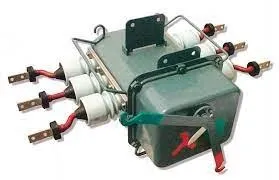
Operating at 24kV for overhead lines, this gas-insulated load break switch offers a maintenance-free and oil-free solution through the utilization of SF6 gas. Housed within a hermetically sealed stainless steel tank, the aforementioned components are securely installed.
Primarily utilized for disconnecting circuits under load conditions due to faults, isolation, or other issues, this switch modulates current flow by mechanically manipulating its contacts at an appropriate speed to either open or close the circuit. Detection of a current surge is achieved by monitoring the voltage drop across the contacts. When this voltage drops below a predetermined threshold, indicating an overload condition, the switch initiates an opening action, breaking the circuit to prevent further increase in current flow until restoration by another circuit breaker.
Throughout the switching operation, whether opening or closing contacts, current flow generates an arc, resulting in the formation of a transient recovery voltage across the switch contacts. Leveraging SF6 gas with its exceptional arc-quenching and dielectric properties, the SF6 gas-insulated Load Break Switch proves invaluable in managing current flow during overload faults.
Type of Load Break Switches
Various types of load break switches are accessible in the market, elaborated as follows:
LBS Type Load Break Switch
The LBS type air load break switch is offered in 3.6kV or 7.2kV configurations, with capacities of up to 600 Amps for 3-pole arrangements. Additionally, versions are available at 3.6kV or 7.2kV with 200 & 400 Amps for 3-pole setups, featuring integrated power fuses. Notably, this LBS air load break switch unit includes power fuses and serves as a striker, a distinctive attribute absent in conventional LBS models.
LBS Type
The striker within this switch functions as a trip mechanism triggered by fuse blowouts. Upon fuse failure, the striker initiates the simultaneous opening of all three poles. Absence of this striker feature in such switches could lead to certain phases remaining energized post-fuse failure, creating hazardous conditions. In instances where switches are equipped with built-in auto trip mechanisms, compatibility with R293B & R290B remote gang-operated mechanisms may not be suitable.
LB Type Load Break Switch
The LB type air load break switch features a compact design, facilitating its installation within confined cubicles. This variant offers enhanced operational safety and improved interrupting performance, owing to the utilization of a rotary arc contact and a redesigned arc chute. Further enhancing versatility, various accessories are integrated using a modular system, enabling straightforward incorporation of gang-operated mechanisms, power fuse frames, and auxiliary switches into the main body of the switch as needed.
LB Type LBS
Moreover, the shunt trip mechanism can now be seamlessly integrated into the core frame, a departure from its previous classification as an accessory. However, it's important to note that the R293B or R290B remote gang-operated mechanisms are incompatible with these shunt trip mechanisms. While the 200AF and 400AF types of LB air load break switches can be equipped with power fuses, it's worth mentioning that if the LBS is rated at 400AF, only power fuses of up to 200 Amps are required.
RF Type Load Break Switch
The RF type load break switch is offered in configurations of 12V, 24V, or 36kV, accommodating currents of up to 1200 Amps for 3-pole setups. Characterized by its design, this LBS features an auxiliary blade, an arc chute, and the primary blade. Positioned within the arc chute, the auxiliary blade is connected to the main blade, enabling simultaneous contact engagement akin to the main blade.
Upon opening of the main blade, the auxiliary blade is temporarily retained in contact within the arc chute. Once the main blade reaches its travel limit, the stored energy within the spring swiftly propels the auxiliary blade back into position against the main blade. This rapid-break mechanism ensures efficient operation, even when manually operated. As the contacts disengage at high speed, the arc is rapidly elongated and cooled by the gas within the arc chute.
SF6 Load Break Switch
The SF6 gas insulated Load Break Switch (LBS) finds primary application in overhead lines operating at voltages up to 24kV. Renowned for their maintenance-free and oil-less operation, these switches rely on SF6 gas. Housed within a stainless steel tank that is hermetically sealed, various components and devices are intricately interconnected to ensure optimal functionality.
The operation of this load break switch can be either manual or motorized, catering to the requirements of fault isolation, automation, and remote control, thus aligning with the needs of power line applications. The SF6 Load Break Switch offers numerous advantages, notably security, high reliability, and effortless installation, making it a preferred choice for various utility and industrial settings.
Comparison: Load Break Switch vs. Circuit Breaker
The disparities between a load break switch and a circuit breaker are elucidated as follows.
|
Load Break Switch |
Circuit Breaker |
| A load break switch (LBS) is engineered to facilitate the establishment or interruption of predetermined currents within an electrical circuit. | A circuit breaker (CB) serves as an electrical safeguarding mechanism, employed to shield an electrical circuit against short circuits or excessive currents. |
| It functions as a disconnection switch. | It serves as an automatically operated electrical switch. |
| Traditionally, load break switches have been categorized into two types: air-blast and SF6. | Three types of circuit breakers are commonly available: standard single-pole and double-pole circuit breakers, ground fault circuit interrupter (GFCI) circuit breakers, and arc fault circuit interrupter (AFCI) circuit breakers. |
| The switch primarily comprises an arc extinguishing chamber, disconnect blade, and operating mechanism. | The circuit breaker incorporates both fixed and moving contacts. |
| It is manually operated. | It can be operated both manually and electrically. |
| There's no need for frequent opening or closing of this switch. | Frequent opening and closing are necessary for this switch. |
| On average, its mechanical lifespan is around 1000 operations. | Its mechanical lifespan averages around 10,000 operations. |
| This switch is unable to interrupt short-circuit currents. | This circuit breaker is capable of interrupting short-circuit currents approximately 20 to 50 times. |
| It handles a low current ranging from 0 to 125A. | It carries a rated current ranging from 0 to 5000A. |
Pros and Cons
Advantages of Load Break Switch:
Cost-effectiveness compared to a two-pole structure.
Enhances security in power grid operation.
Effortlessly controls power supply by toggling ON and OFF.
Protects transformers using HRC fuses.
Simple design, user-friendly operation, and reliable functionality.
Disadvantages of Load Break Switch:
Higher initial cost.
Requires space for installation.
Lower security compared to alternatives.
Applications of Load Break Switch
The utilization of load break switches spans across various domains, encompassing the following:
Designed to establish or interrupt specified currents.
Integral to power distribution grids, often integrated with reclosers to augment control capabilities.
Primarily employed for disengaging electrical circuits under load conditions.
Widely deployed in diverse applications such as capacitor banks, transformer switching, and ring main units (RMUs).
Deployed for the energization or de-energization of circuits featuring limited line charging or transformer exciting currents.
In summary, load break switches offer a comprehensive solution characterized by their cost-effectiveness, reliability, security, simplistic structure, and ease of installation and operation.
As for your question, an air blast circuit breaker is a type of circuit breaker that uses compressed air to extinguish the arc resulting from the interruption of current flow in the circuit. Would you like more details on how it works or its applications?
Related Articles
Principle, Structure and Fault Analysis of Centrifugal Switch
Switching Diodes: Definitions, Principles, Applications, and Future Trends
Exploring Solenoid Switches: Principles and Applications
Operation & Fault Handling of High Voltage Switchgear Explained


