


Zero Speed Switch : Principle & Its Applications
Monitoring the velocity of motors and elevators holds significant importance. Consequently, alterations in the velocity of any electrically powered apparatus due to various factors such as malfunctioning transmission parts, underloading, overloading, etc., may occur. Hence, integrating a velocity monitoring mechanism within an open-loop control system proves invaluable, facilitating the generation of alerts or shutting down the electric motor as needed. Conversely, in closed-loop control setups like V/F drives or D.C. drives, feedback becomes imperative for executing suitable measures. This piece provides an overview of the operational principles of a zero-speed switch and its applications.
What exactly is a Zero Speed Switch?
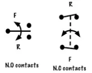
A zero-speed switch, also known as a speed-actuating sensing switch, serves to identify the rotational speed of shafts in various settings such as motors, conveyors, power plants, and industries encompassing sugar production, paper manufacturing, textile processing, cement production, and more. Below is the symbol representing the zero-speed switch.
Once employed in conveyor belts, this switch halts conveyor movement upon detecting a drop in belt speed below the predetermined threshold. Likewise, in electric motors, it identifies slow shaft rotation or jamming to initiate motor shutdown.
These switches leverage various technologies such as electronic magnetic, proximity, or electronic. Electromechanical speed switches serve as speed indicators and are directly linked to the system, operating by mechanically opening or closing a set of contacts in response to the rotational speed of the switch shaft.
Likewise, electronic zero-speed switches are directly coupled and serve as speed indicators, regulating a set of contacts through either a relay or an electronic circuit.
Zero Speed Switch Operational Concept
A zero-speed switch comprises a sensor and a controller, with its functionality primarily reliant on these components. Positioned in close proximity to the controller, the sensor detects any irregularities and promptly relays a command to the controller. Subsequently, the controller initiates the appropriate response based on the received signal.
The attributes of a zero-speed switch primarily encompass specifications such as input shaft speed, operational and temperature ranges, trip set-point, field adjustability, operating conditions, relay contact rating, and operating voltage. For numerous applications, these switches are designed to be weatherproof, dustproof, or explosion-proof.
Zero Speed Switch Connection Diagram & Operation
The connection layout for a zero-speed switch is depicted below. Typically, plugging entails the sudden cessation of motor motion by swiftly shifting it into reverse upon pressing the stop button. In this discussion, we'll delve into the zero-speed switch's application in facilitating plugging within a circuit.
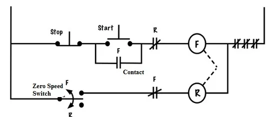
In the aforementioned schematic, we incorporate a basic start-stop setup alongside forward and reverse functionalities, incorporating fundamental interlocks designated as 'R' and 'F', along with a zero-speed switch. This particular zero-speed switch operates via centrifugal force.
When the motor within the circuit moves in the forward direction, the switch is elevated, while a sudden reversal of the motor's motion causes it to be lowered into position. The arrow symbol within the circuit signifies the centrifugal motion associated with the zero-speed switches themselves.
The zero-speed switch employed in this setup is activated by centrifugal forces, directly connected or via a belt to the motor's shaft. This facilitates plugging action within the circuit. Configured in normally open (NO) mode, the switch responds to any motion of the motor shaft, causing the contacts to adjust and close.
Upon pressing the start button, the motor operates in the forward direction under normal conditions. This energizes the forward coil, closing the normally open contact in parallel with the start button, while simultaneously opening the normally open (NO) electrical interlocks in series with the reverse coil.
In this circuit, the motor operates continuously, functioning as a standard 3-wire setup that offers low-voltage protection until either an overload occurs or the stop button is pressed.
As the motor shaft rotates, the zero-speed switch contacts adjust, closing the forward contact. This contact is linked in series with the reverse coil, but remains unenergized as long as the electrical interlock remains open.
Pressing the stop button de-energizes the forward coil, halting the armature's motion and causing all associated contacts with the forward coil to return to their normal state, including the normally closed (NC) electrical interlock.
Despite the stop command, the motor shaft continues to rotate in the forward direction due to inertia, keeping the normally open (NO) zero-speed switch contacts closed. Instantly pressing the stop button strengthens the reverse coil, momentarily driving the motor in reverse and counteracting its forward momentum, swiftly bringing it to a halt.
As the motor shaft starts moving in reverse, the forward contacts of the switch open, allowing the reverse coil to de-energize before the motor gains significant momentum in the reverse direction. Thus, the motor is effectively plugged and stopped.
Advantages and Disadvantages of zero-speed switch
The benefits of zero-speed switches are as follows:
1. Easy speed adjustment.
2. Equipment safeguarding against damage.
3. Non-contact speed detection.
4. Incorporation of built-in bypass time delay functionality.
5. Reduction in maintenance requirements and downtime.
6. Prevention of roller wear and tear or coupling misalignment.
7. Speed adjustment possible within optional ranges from 1 to 5000 RPM.
8. Sensor functionality in environments with dirt, water, oil, chemicals, and dust.
9. Ability to discern direction and speed across multiple locations from a single point.
10. Capability for sensing direction and speed at various locations from a central point.
11. Operation without direct contact with machinery, leading to minimal moving parts and lower maintenance needs.
The disadvantages of zero-speed switches are outlined below:
1. Requirement for a bypass arrangement to monitor speed conditions during machine startup.
2. Possibility of equipment momentarily dropping speed during operation due to various factors, necessitating the inclusion of a built-in time delay to prevent tripping.
3. Potential speed fluctuations in devices powered by motors due to overload, transmission parts breakage, underload, and other factors.
The utility of zero-speed switches spans various applications:
1. Monitoring conveyor system speed.
2. Speed monitoring in industrial machinery such as rolling mills, crushers, stirrers, and mixers.
3. Activation of relay contacts at predetermined speeds to facilitate control actions including under-speed protection, over-speed protection, and zero-speed protection.
4. Deployment across numerous industrial manufacturing plants.
5. Speed monitoring in crushers, conveyors, rolling mills, mixers, stirrers, agitators, and screw conveyors.
6. Utilization in both food-grade and heavy industrial-grade settings.
7. Availability for wash-down duty or hazardous environments.
8. Adoption in thermal power stations, steel plants, fertilizer plants, coal factories, tile factories, heating system blowers, automobile industries, food industries, cement factories, and textile industries, among others.
So, that covers the functionality of zero-speed switches along with their various applications. These switches are categorized into two types based on the power supply they receive. The first type is the interrupted power type, receiving power only during the period when power is supplied to the motor. The second type is the continuous power type, which maintains a continuous power supply to the switch. Installation of these switches typically revolves around the construction of rotating parts or shafts where speed observation is required. Here's a question for you: What's another term for the zero-speed switch?
Related Articles
Principle, Structure and Fault Analysis of Centrifugal Switch
Switching Diodes: Definitions, Principles, Applications, and Future Trends
Exploring Solenoid Switches: Principles and Applications
Operation & Fault Handling of High Voltage Switchgear Explained


