


AD620 Instrumentation Op-Amp for Low Noise Signal Gain
Low noise signal amplification is paramount in precision analog electronics since they are essential in measuring and performing. AD620 is a well-regarded instrumentation amplifier amongst engineers and hobbyists due to its potential to amplify low-level differential signals, low noise amplitude and low power requirement. The qualities, functionality, usages, and comparison of the AD620 with other instrumentation amplifiers are discussed in this paper.
Introduction to AD620
Analog Devices designed the AD620; a low-cost high-precision instrumentation amplifier. It has low input bias current, outstanding Common Mode Rejection Ratio (CMRR) and gain can be easily configured, it is suited in applications where small signal amplification is required at minimum distortion or noise. AD620 is a reliable performer whether it is industrial signal conditioning or working on a medical sensor interface.
Key Features of AD620
The AD620 offers an outstanding balance of performance and simplicity:
- Low Input Offset Voltage: The typical offset voltage of 50 M is lower so that the signal can be measured with few errors.
- High CMRR: CMRR more than 120 dB rejects common mode noise up to 120dB in a noisy environment or long sensor lengths.
- Low Power Consumption: Requires only 1.3 mA supply current, and makes it suitable for battery-powered and power-efficient designs.
- Wide Supply Range: Diversifies the design by operating between and ±18 V or single supply working between 4.6 V to 36 V.
- Adjustable Gain: The gain of 1 to 1000 gain is preset using one external resistor, which makes circuit design easier.
- Low Noise: Low 9 nV/ 1 kHz 4Hz input noise enables accurate amplification of signals used at low levels of sensitivity.
Internal Architecture and Working Principle
The AD620 uses a classic three-op-amp instrumentation amplifier configuration consisting of two buffer amplifiers followed by a differential amplifier stage. This architecture provides:
- High input impedance
- Precise gain control via a single resistor between pins 1 and 8
- Low output impedance
- Excellent common-mode rejection
The gain is determined by the resistor using the formula:
Gain = 1 + (49.4 kΩ / RG)
This simplicity reduces component count while ensuring precise and repeatable gain settings.
Application Circuits Using AD620
The AD620 is widely used in various real-world applications:
Biomedical Signal Acquisition
The AD620 works ideal in amplifying low-level signals of ECG, EEG, and EMG systems. These biomedical signals are very susceptible and noisy. With its minimal input bias current and high noise rejection, the AD620 provides clean signal amplification and is well suited to medical diagnostic and monitoring applications.
Strain Gauge Measurement
Strain gauges are used in load cells and pressure sensors to give very small differential voltages produced in the form of a Wheatstone bridge. Such low-level signals can be amplified very precisely by the AD620, rejecting common-mode noise and simplifying the signal conditioning required, which is critical in structural and mechanical sensing.
Thermocouple Amplification
Thermocouples are the source of some very small voltages in the range of microvolts. AD620 is now a good choice to amplify such signals in temperature control in HVAC systems, industrial controls, and scientific equipment. It allows one to easily achieve proper temperature readings due to its low offset and tunable gain.
Industrial Process Control
AD620 is useful in adverse factory conditions to condition analog signals in devices such as RTDs and pressure transmitters. This is because of its high input impedance and immunity to noise, which facilitates effective transmission of signals even on long cables or even in systems of differing grounds.
Data Acquisition Systems (DAQs)
The AD620 is often used to amplify weak sensor signals before digitization. In DAQ systems, it ensures signals are within the ADC range while maintaining linearity. Its compact size and gain adjustability make it ideal for portable instruments and multi-channel data logging systems.
Example Circuit:
A typical ECG front-end may use AD620 with a gain of 1000, powered by a single 5 V supply, and include filtering to eliminate 50/60 Hz noise.
Advantages of AD620 over Other Instrumentation Amps
|
Feature |
AD620 |
INA128 |
AD623 |
LM324 (general op-amp) |
|
CMRR (min) |
100 dB |
100 dB |
95 dB |
< 70 dB |
|
Gain Adjustment |
Single resistor |
Single resistor |
Single resistor |
External circuit needed |
|
Input Offset Voltage |
50 µV (typical) |
50 µV |
200 µV |
> 2000 µV |
|
Power Supply |
±2.3 V to ±18 V |
±2.25 V to ±18 V |
2.7 V to 36 V |
±1.5 V to ±16 V |
|
Cost/Performance |
Excellent |
Good |
Lower cost |
Lowest performance |
AD620 Electrical Characteristics and Pinout
Package Types:
DIP-8 (Dual Inline Package)
SOIC-8 (Surface Mount)
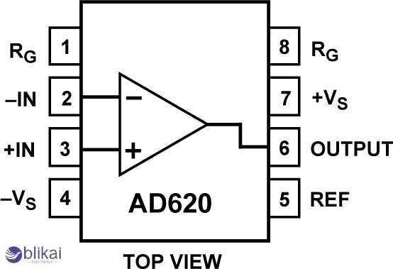
Pinout Description:
|
Pin |
Name |
Description |
|
1 |
RG |
Gain resistor terminal |
|
2 |
-IN |
Inverting input |
|
3 |
+IN |
Non-inverting input |
|
4 |
-VS |
Negative power supply |
|
5 |
Ref |
Output reference |
|
6 |
Output |
Amplified output |
|
7 |
+VS |
Positive power supply |
|
8 |
RG |
Gain resistor terminal |
Key Specs:
Input impedance: 10 GΩ
Output voltage swing: Typically within 50 mV of rails
Slew rate: 0.3 V/μs
Bandwidth: \~1.2 MHz at G=1
Design Tips for AD620-Based Circuits
To ensure optimal performance, follow these design recommendations:
- Gain Resistor Selection: Use precision resistors for stable gain.
- Decoupling Capacitors: Place 0.1 µF ceramic caps close to the power pins.
- Grounding: Use a single-point ground to reduce ground loops.
- Layout: Keep input traces short and shielded; avoid running them near noisy digital signals.
- Reference Pin: Tie to ground or bias voltage to shift output level as needed.
Troubleshooting Common Issues
|
Issue |
Possible Cause |
Solution |
|
Output saturates near rail |
Output reference pin is floating |
Connect Ref pin to ground or Vref |
|
Excess noise in output |
Poor PCB layout or unshielded inputs |
Improve layout, use twisted pair wires |
|
Incorrect gain |
Wrong RG resistor value |
Recalculate using gain formula |
|
Distorted output waveform |
Input signal outside input common-mode range |
Check input voltage limits |
FAQs about the AD620 Instrumentation Amplifier
Q1: Can a single supply power AD620?
Indeed, the AD620 can operate with a single supply of 4.6 V. This is perfect for battery-powered or portable ones. J, Just make certain the input bias of the reference pin is correct so as to maintain the output at range.
Q2: What is the maximum gain of the AD620?
The AD620 has a gain of up to 1000x through an external resistor. This also suits it very well to amplify very small signals as with a sensor or biomedical electrodes.
Q3: How do I calculate the resistor for a specific gain?
Use the formula: Gain = 1 + (49.4 kΩ / RG). For a gain of 101, RG = 494 Ω. Precision resistors are recommended for stable and accurate results.
Q4: Can AD620 be used in ECG or medical applications?
Yes. It contains low noise and high CMRR and input impedance which makes it suitable in amplification of biomedical signals ECG, EMG etc.
Q5: Is it suitable for differential signal amplification?
Absolutely. AD620 is a differential optimum circuit and offers a good common-mode noise rejection, due to which it is trusted in the sensor and data acquisition.
Conclusion
AD620 instrumentation amplifier is a powerful and transparent amplifier with low noise gain required in designs of analog circuits. It has a low offset and broad supply range and is easily gain-adjusted, therefore making it very good in medical, industrial and sensor applications. AD620 provides excellent and stable performance whether you are prototyping or developing a commercial system.


