


What Arduino Mega 2560 is and How it works
The Arduino board is an open-source microcontroller board based on the Atmega 2560 microcontroller. This board's development environment uses the processing or wiring language. These boards have revitalized the automation industry with their easy-to-use platform, enabling individuals with little to no technical background to start learning basic programming and operating the Arduino board. These boards can be used to create standalone interactive objects or connect to software on your PC like MaxMSP, Processing, and Flash. This article provides an introduction to the Arduino Mega 2560 board, including its pin diagram and specifications.
What is an Arduino Mega 2560?
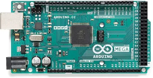
The microcontroller board known as "Arduino Mega" is based on the ATmega2560 microcontroller. It features 54 digital input/output pins, with 16 pins as analog inputs, 14 pins as PWM outputs, 4 hardware serial ports (UARTs), a 16 MHz crystal oscillator, an ICSP header, a power jack, a USB connection, and an RST button. This board includes everything necessary to support the microcontroller. It can be powered by connecting it to a PC via a USB cable, a battery, or an AC-DC adapter. Additionally, the board can be protected from unexpected electrical discharges by using a base plate.
The SCL and SDA pins of the Mega 2560 R3 board are located next to the AREF pin. Additionally, there are two new pins situated near the RST pin. One pin is the IOREF, which allows shields to adapt to the voltage provided by the Arduino board. The other pin is not connected and is reserved for future use. These boards are compatible with all existing shields and can adapt to new shields that utilize these additional pins.
Arduino Mega Specifications
The specifications of the Arduino Mega are as follows:
- Microcontroller: ATmega2560
- Operating Voltage: 5 volts
- Recommended Input Voltage: 7 to 12 volts
- Input Voltage Range: 6 to 20 volts
- Digital Input/Output Pins: 54 (15 of which provide PWM output)
- Analog Input Pins: 16
- DC Current per Input/Output Pin: 40 mA
- DC Current for 3.3V Pin: 50 mA
- Flash Memory: 256 KB (8 KB used by bootloader)
- SRAM: 8 KB
- EEPROM: 4 KB
- Clock Speed: 16 MHz
- USB Host Chip: MAX3421E
- Board Length: 101.52 mm
- Board Width: 53.3 mm
- Board Weight: 36 g
Arduino Mega Pin Configuration
The pin configuration of the Arduino Mega 2560 board is shown below. Each pin has a specific function associated with it. All analog pins can be used as digital I/O pins. Using this board, an Arduino Mega project can be designed. These boards offer more flexible work memory space and processing power, allowing them to work with various sensors without delay. Compared to other Arduino boards, the Arduino Mega is physically superior.
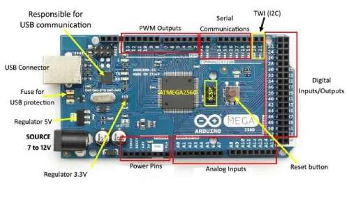
Pin 3.3V & 5V
These pins provide regulated output voltage, approximately 5V. This regulated power supply (RPS) powers the microcontroller and other components on the Arduino Mega board. The 5V can be sourced from the Vin pin of the board, another regulated voltage supply, or a USB cable, while 3.3V is available from the 3.3V pin, with a maximum current draw of 50mA.
GND Pin
The Arduino Mega board has 5 GND pins, any of which can be used as needed for the project.
Reset (RST) Pin
The RST pin is used to reset the board. By setting this pin to low, the board will be rearranged.
Vin Pin
The input voltage supplied to the board can range from 7 to 20 volts. The voltage provided through the power jack can be accessed via this pin, and it will automatically be regulated to 5V for the board's use.
Serial Communication
The serial pins TXD and RXD are used for transmitting and receiving serial data. TX indicates data transmission, while RX indicates data reception. The board supports four serial communication combinations:
- Serial 0: TX (1) and RX (0)
- Serial 1: TX (18) and RX (19)
- Serial 2: TX (16) and RX (17)
- Serial 3: TX (14) and RX (15)
External Interrupts
External interrupts can be generated using six pins: interrupt 0 (pin 2), interrupt 1 (pin 3), interrupt 2 (pin 21), interrupt 3 (pin 20), interrupt 4 (pin 19), and interrupt 5 (pin 18). Interrupts can be triggered by various conditions, such as a low value, a rising or falling edge, or a change in value on the interrupt pins.
LED
The Arduino board includes an LED connected to digital pin 13. This LED can be controlled based on the high and low states of the pin, allowing you to test and modify programming skills in real-time.
AREF
AREF stands for Analog Reference Voltage, which is the reference voltage for analog inputs.
Analog Pins
The board includes 16 analog pins, labeled A0-A15. All analog pins on this board can also be used as digital I/O pins. Each analog pin offers a 10-bit resolution, measuring from GND to 5 volts. This range can be adjusted using the AREF pin and the analogReference() function.
I2C
I2C communication is supported by pins 20 and 21. Pin 20 represents the Serial Data Line (SDA), which holds the data, while pin 21 represents the Serial Clock Line (SCL), which provides data synchronization among devices.
SPI Communication
SPI (Serial Peripheral Interface) is used to transmit data between the controller and other components. The four pins used for SPI communication are MISO (50), MOSI (51), SCK (52), and SS (53).
Dimensions
The Arduino Mega 2560 board measures 101.6 mm (4 inches) in length and 53.34 mm (2.1 inches) in width. It is slightly larger than other types of boards available in the market. However, the power jack and USB port extend slightly beyond these dimensions.
Shield Compatibility
The Arduino Mega is compatible with most shields used with other Arduino boards. Before using a shield, ensure its operating voltage matches the board's voltage, typically 3.3V or 5V. Shields with a higher operating voltage can damage the board. Additionally, the shield's distribution header should align with the distribution pins of the Arduino board, allowing for easy connection and operation.
Programming
Programming the Arduino Mega 2560 is done using the Arduino IDE (Integrated Development Environment), which supports the C programming language. The sketch (code) is written in the IDE, then uploaded to the Arduino board via a USB cable.
An Arduino Mega board includes a bootloader, which eliminates the need for an external burner to program the Arduino board. The bootloader communicates using the STK500 protocol.
After compiling and burning an Arduino program, you can disconnect the USB cable to remove the power supply from the board. When using the Arduino board for a project, power can be supplied via the power jack or the Vin pin.
Another feature of the Arduino Mega board is multitasking. Although the Arduino IDE software doesn’t support multitasking, you can use additional operating systems like RTX and FreeRTOS to write C programs for this purpose. This allows you to create custom programs using the ISP connector.
In summary
This is an overview of the Arduino Mega 2560 datasheet. It is an upgrade from the older Arduino Mega board. Due to its numerous pins, it is generally not used for simple projects but is found in complex applications such as temperature sensing, 3D printers, IoT applications, radon detectors, and real-time data monitoring. Here is a question for you: What are the specifications of the Arduino Mega 2560 board?


