


What is BT136 600E TRIAC? Pinout and Applications
In the BT136 600E TRIAC, the term TRIAC stands for "TRIode for AC" or Alternating Current. This device is a three-terminal, five-layer power semiconductor. It features a controlled SCR pair connected in opposite parallel configurations on the same IC. As TRIAC conducts current flow in both directions, it is known as a bidirectional device. Various types of TRIACs are available on the market, including the BT136 600E TRIAC, such as BT137, BT138, and others. This article provides an overview of the BT136 600E TRIAC, covering its pinout, specifications, working principles, and applications.
What is BT136 600E TRIAC?
The BT136 TRIAC supports a maximum terminal current of 4A and has a low gate threshold voltage, making it suitable for driving through digital circuits. TRIACs are bidirectional switching devices frequently used in AC-based applications. Therefore, if you need to control an AC load below 6A using a microprocessor or microcontroller, the BT136 600E TRIAC is ideal for your application.
This specialized semiconductor device, such as the TRIAC, replaces the SCR structure to provide bidirectional control. As a bidirectional switching device, it is used to control AC power accurately and efficiently. Consequently, these devices are commonly used in AC circuits, motor speed controllers, light dimmers, pressure control systems, and other AC control devices.
Pin Configuration of BT136 TRIAC
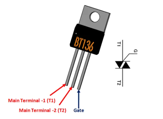
The pin configuration of the BT136 600E TRIAC includes the following:
- Pin1 (Main Terminal1): This terminal is connected to the neutral/phase of AC mains
- Pin2 (Main Terminal2): This terminal is connected to the neutral or phase of AC mains
- Pin3 (Gate): This terminal is used to activate the silicon-controlled rectifier
Features & Specifications
The features and specifications of the BT136 600E TRIAC include the following.
- The maximum supply current through the terminal is 4A
- The voltage at the On-state gate is 1.4V
- Gate trigger current is 10mA
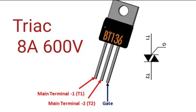
- The maximum terminal voltage is 600V
- Holding current is 2.2mA
- The latching current is 4mA
- The available package is TO-220
- The equivalent BT136 600E TRIAC is BTA08-600B, while alternate BT136 600E TRIACs include BTA16, Q4008, BT139, and BT169.
Precautions while using a BT136 600E TRIAC
The following precautions need to be taken while using a BT136 600E TRIAC:
- Designing TRIAC circuits that handle AC voltage must be done very carefully. TRIAC circuits can experience a phenomenon known as Rate Effect, which occurs when the TRIAC switches normally and an abrupt high voltage appears at any terminal, potentially damaging the TRIAC. This can be mitigated using a snubber circuit.
- Another issue is the backlash effect caused by the accumulated capacitance between the two terminals of the TRIAC, such as MT1 and MT2. As a result, the TRIAC may not switch ON even if voltage is applied to the gate terminal. This problem can be resolved by placing a resistor in series with the capacitance for discharge.
- When controlling output AC voltage for speed control or dimmer applications, the Zero Crossing technique is always recommended. The TRIAC in switching circuits is susceptible to EMI interference and harmonics, so it must be isolated from other digital electronics. There is a risk of backward current when the TRIAC controls inductive loads; therefore, an alternate discharge path should be provided for the inrush current from the load to drain.
AC Power Control Circuit using BT136 600E TRIAC
The circuit diagram of AC power control with the BT136 600E TRIAC is shown below.
The TRIAC is an ideal power electronics switch used in switching applications as it controls the current flow in both cycles of an alternating signal. The main advantage of this is that it is less expensive compared to the back-to-back thyristor circuit. If you need to control up to 600V of voltage and 4A of current, the BT136 600E TRIAC and back-to-back thyristor are recommended to ensure the circuit functions properly.
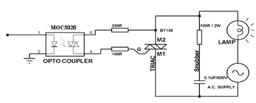
High voltage devices controlled with power electronics devices that are optically isolated provide voltage control benefits. Here, the simple BT136 TRIAC circuit, along with the MOC3021 Optocoupler, can control high voltage devices using a microcontroller.
For instance, an Arduino board can control high voltage devices or bulbs like 230V or 220V. This circuit can also be used for dimming and speed control applications with a PWM signal using Arduino. When the TRIAC includes a valve in both directions, this circuit is mainly used for AC and DC applications.
The required components to build this circuit are: R1 = 330 Ohms, R2 = 360 Ohms, R3 = 470 Ohms, R4 = 39 Ohms, C1 = 50nF or 0.05μF, 250V or 400V, C2 = 10nF or 0.01μF, 250V or 400V, U1 = MOC3021 or 3031 or 3051, U2 = 6-pin IC Socket, BT136 TRIAC, lamp with 100W 230V, 4 cm × 10 cm PCB, flexible wire, soldering iron, metal wire, 2-pin PBT connector, holder for lamp, etc.
The TRIAC operates mainly in two conditions: ON and OFF. In the ON condition, a voltage of 3.3V or 5V is supplied through a microcontroller to the MOC3021 optocoupler, which has GaAs IR emitting diodes on both pin-1 and pin-2.
This type of diode generates IR light, activating the light-activated Si bilateral switch optically coupled on pins 4 and 6, allowing current to flow between them. This current supply provides current to the TRIAC gate's pin3, enabling the TRIAC to conduct the main current supply between MT1 and MT2.
In the OFF condition, when no voltage is applied between the optocoupler's pins 1 and 2, pins 4 and 6 act as an open switch, preventing current flow between them. Consequently, no current reaches the TRIAC gate, stopping its conduction.
Advantages
The advantages of the TRIAC include the following:
- - When positive and negative polarity voltages are applied to the gate terminal, it will be activated.
- - It can function and control AC waveforms in both half cycles.
- - A TRIAC uses a single large heat sink compared to the anti-parallel design, which requires two small heat sinks. This conserves both cost and space in AC power applications.
- - In direct current applications, silicon-controlled rectifiers must be connected with a parallel diode for protection against reverse voltage. However, the TRIAC can function without a diode, providing secure breakdown in any direction.
Disadvantages
The disadvantages of the TRIAC include the following:
- - More care is needed when choosing a gate trigger circuit because a TRIAC device activates in both biased conditions.
- - They are less reliable compared to thyristors.
- - They have a lower dv/dt rating compared to thyristors.
- - The switching frequencies of TRIACs are extremely low.
Where to use/Applications
The applications of TRIAC include the following:
- Due to their bidirectional control of alternating current, these components are utilized in various applications such as AC controllers, fans, heaters, static switches with three positions, triggering devices for silicon-controlled rectifiers, light dimmers, etc.
- TRIACs are used as switches.
- They serve as high-power switches.
- They are employed for phase control.
- Used in strobe lights.
- Applied for speed control of AC motors.
- Utilized in circuits for noise coupling.
- Control of AC loads with MPU or MCU.
- Power control of AC or DC.
Thus, this provides an overview of the BT136 600E TRIAC datasheet, covering its pin diagram, features, circuit working, advantages, disadvantages, and applications. Here's a question for you: What is the difference between TRIAC and DIAC?


