


Inductor Symbol in Circuit Diagrams: Guide to Electronic Components
Introduction to Inductor Symbols
One of the fundamental passive components in electronics is the inductor, which is used to store energy in a magnetic field when an electric current is applied through the inductor. They find extensive application in filters, power storage, tuning circuits and in power conversions. Although it is important to know the physical aspect of an inductor, such as its physical structure and characteristics, it is also essential to know how to read circuit charts. Circuit symbols are a standardized language that enables engineers, hobbyists and students to intuitively recognize components without considering the actual hardware. The use of the inductor symbol facilitates the avoidance of errors in circuit design, assembly and troubleshooting and bridging the gap between theory and practice.
The Standard Inductor Symbol in Circuit Diagrams
The common symbol of an inductor is that of a combination of loops or coils, a symbol which resembles the physical windings of wire in a real inductor. This visual representation can be used to find the component quickly in schematics. Depending on the standard to be used, some of the diagrams used involve a zig-zag coil, whereas others illustrate a smooth, curvy coil. These variations are essential to understand since a misunderstanding of the symbol may cause wrong conclusions regarding the operation of the component. Moreover, various areas have a somewhat different convention. The most commonly used standard, known as ANSI in the United States, usually indicates the coil as a zig-zag line, but the standard used in Europe (IEC) usually indicates it as a smooth curved line. The meaning of both symbols is the same: an inductor that stores the energy in a magnetic form and is resistant to alteration of current.
Variants of Inductor Symbols and Their Meanings
Air-Core Inductor Symbol
An air-core inductor is made out of no magnetic material in the core. The symbol is a plain coiled line with no other marks in it, and it suggests the lack of a magnetic core. They are great inductors used in high-frequency applications like radio frequency (RF) applications, oscillators, and signal filtering. Air-core inductors do not saturate magnetically and therefore can be used consistently at higher frequencies. In schematics, the quick identification of the basic shape of the coil will tell the engineers and technicians what type of inductor is used and how it is most probably applied in the circuit.
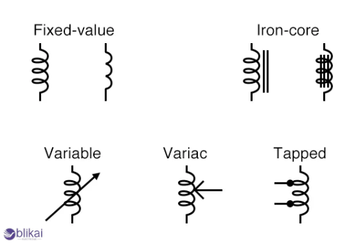
Iron-Core Inductor Symbol
Inductors with an iron or ferrite magnetic core are called iron-core inductors. In schematics, they are defined by a coil symbol with two short parallel lines next to it denoting an existent magnetic core. They find extensive application in power supplies, low-frequency filters and transformers. The core increases the inductance so that the inductor can be able to store additional energy without the need to be larger in size. Determining this symbol is essential to the correct choice of circuit design since replacing an inductor with an air core will reduce the efficiency and stability of the circuit.
Variable Inductor Symbol
A variable inductor enables the user to adjust the inductance of the inductor to adjust the behavior of a circuit. It has a symbol, a regular coil containing an arrow passing through or across it, meaning that it is variable. Variable inductors are usually used in radio tuners, frequency-selective filters and adjustable oscillators. Such a symbol is important in schematics where fine control and adjustment are needed, as it would be impossible to use a fixed inductor instead of a variable inductor without breaking the circuit or turning it off.
Coupled Inductors and Transformers
In cases where there is magnetic coupling or coupling between two inductors, such as in transformers, the schematic representation is a representation of two coils, connected by a dotted line or magnetic tie. This notation is used to denote mutual inductance, and thus energy can be transferred between coils without electrical contact. The coupled inductors play an important role in the conversion of AC to DC, signal isolation and impedance matching. Knowledge of this symbol is important to understand the flow of power and signal in a circuit, especially where there are transformers or coupled filters.
Practical Importance of Inductor Symbols in Circuit Design
The symbols used in circuit diagrams to represent inductors are not merely abstract models; they are also useful in real-life circuit design and implementation. These symbols have to be correctly interpreted so that designers use the correct component in a particular application, be it noise filtering, energy storage, or resonance frequency selection. Interpretation of a symbol might be mistaken, leading to impaired connections, overheating or electrical circuit breakdown. As an example of a power supply with an iron-core inductor, poor voltage regulation or loss of energy may be caused by using an air-core inductor instead of an iron-core inductor at low frequencies. When used correctly, symbol recognition can also give the technician a faster and more accurate way of troubleshooting circuits by helping them spot problems without having to physically strip devices.
Tips for Reading and Drawing Inductor Symbols
Identifying Inductors
Inductors in schematics are often represented as coiled lines, occasionally with other marks such as arrows or parallel lines. These are the details to pay attention to the distinctions between air-core, iron-core and variable inductors. The context also plays a role: how they are designed (housed in filters, oscillators or power circuits) may give some ideas as to their purpose.
Common Mistakes
Novices will frequently mix up inductors and resistors because of analogous zig-zag diagrams in certain schematic standards. The other error is not to consider the arrow in the symbols of the variable inductor, and this can be misleading to replacing a fixed inductor wrongly. Knowing every variation of symbols minimizes mistakes and increases the precision of the design.
Conclusion
Learning to identify the inductor symbols in circuit diagrams is an essential element for an individual working in the field of electronics. From the design of the circuit to its construction and maintenance, knowledge of such symbols will guarantee proper implementation, effective troubleshooting, and enhance overall performance. The ability to connect theoretical information with practical schematic reading enables engineers, students and hobbyists to work more efficiently and confidently. Learning the symbols of the inductors is also the gateway to learning other component symbols, which will enable you to gain a complete understanding of the complex electronic systems and become electronics literate.
FAQ
What does an inductor symbol look like in a circuit diagram?
The standard inductor symbol is in the form of a coiled line, which depicts the winding of wires. They vary from zig-zag lines (ANSI standard) and smooth arcs (IEC standard). Other markings, such as arrows or parallel lines, are used to show variable or iron-core inductors.
How can I tell the difference between air-core and iron-core inductors in schematics?
Simplified coils without additional lines are referred to as air-core inductors. Inductors with iron cores contain two parallel short lines on each side of the coil, which represent the magnetic core.
What is the symbol for a variable inductor?
A variable inductor can be represented by a coil through which an arrow is run or crossed. The arrow shows that the inductance may be fine-tuned on circuits.
How are coupled inductors or transformers shown in circuit diagrams?
Coupled inductors are shown to be two coils with a dotted line or link between them, indicating the magnetic coupling. This implies the mutual inductance of energy transfer between coils.
Why is it important to recognize inductor symbols?
The use of inductor symbols leads to the correct selection of the component, assembling of the circuit, easier troubleshooting, and understanding of schematics, particularly in filtering, tuning, and power applications.
Can inductors be confused with other components in schematics?
Yes. Beginners sometimes confuse inductors with resistors due to similar zig-zag representations in certain standards. Always check context, symbol variations, and surrounding components to avoid mistakes.
Are there software tools to help learn inductor symbols?
Yes. KiCad, Eagle, Proteus, and online symbol libraries are also tools that can be used to practice the reading and drawing of schematic symbols (such as inductors), assisting a user in learning to master circuit diagrams.
Do inductor symbols indicate the component’s value?
No, the inductance of the symbol is not equal to the value of inductance. The values are normally denoted alongside the symbol, e.g., 10 uH, and the symbol itself represents the type of inductor used (air-core, iron-core or variable).
What is the difference between ANSI and IEC inductor symbols?
ANSI (common in the U.S.) typically inductors are made by zig-zag lines, and IEC (European standard) uses smooth, rounded coils. The two depict one and the same element but with various drawing conventions.
How can understanding inductor symbols improve electronics learning?
Learning symbols fills the gap between theory and actual circuit design. It aids students, engineers and hobbyists in reading schematics correctly, finding components fast and designing or troubleshooting circuits.
Some images are sourced online. Please contact us for removal if any copyright concerns arise.


