


Potentiometer Symbol Explained for Beginners with Applications
Introduction to Potentiometers
A potentiometer (sometimes called a pot) is one of the most prevalently employed electronic elements in simple and complicated frameworks. In most senses, it is a kind of variable resistor, by the means of which the user can change the resistance in an electrical circuit manually. By making this adjustment, the voltage and current in the circuit can be altered, giving the ability to modulate any number of functions into the circuit like the volume, brightness, or sensor calibration etc.
It is essential to come to grips with a potentiometer symbol as it is used almost everywhere where there is any adjustable control in the shape of a schematic. It becomes easily complex and open to errors in the determination or drafting of this circuit unless this symbol is known, its uses and how it works. This work aims at providing the info that will guide a novice through the essentials of the potentiometer symbol, the way to read it on diagrams and the sites of its practical application.
What Does the Potentiometer Symbol Look Like?
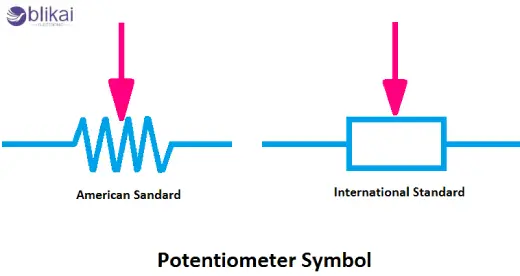
This potentiometer symbol in circuit diagram depicts the three most important terminals of the component and their interaction in electricity. The most popular looks like a resistor symbol (zigzag or a rectangular box) connected with an arrowed tip at the central part of the resistor body. And the following arrow is vital - this is the wiper terminal, the sliding contact that moves across the resistive element to change the resistance.
Resistive Track: The main body shown as a zigzag line or rectangle represents the resistive material inside the potentiometer.
Fixed Terminals: Located at either end of the resistive track, these two terminals connect to the fixed ends of the resistor.
Wiper Terminal: Shown as an arrow touching the resistive track, the wiper moves physically inside the potentiometer to tap the voltage at varying points.
Occasionally, the symbol may be varied, at least to indicate potentiometers of a different type, e.g. rotary or linear, but the same basic concept prevails. As an example, a sign of a rotary potentiometer can be accompanied by a curved arrow near it to reflect the rotation.
How to Read and Interpret the Potentiometer Symbol
In viewing a circuit schematic, one has to ensure that each of the terminals of the potentiometer symbology is correctly recognized to make sense of the circuit operation. That should be understood this way:
Terminal 1 and Terminal 3: These connect to the fixed ends of the resistor element inside the potentiometer. They typically link to the voltage source and ground or another part of the circuit.
Terminal 2 (Wiper): The middle terminal, shown with the arrow, adjusts its position along the resistive track, effectively dividing the voltage between terminals 1 and 3. By moving the wiper, the output voltage or resistance changes continuously within the potentiometer’s range.
Riders confused with the wiper as a fixed terminal or got ones confused, making mistakes in the terminals to use are sometimes committed by the beginners. The symbol is a wiper terminal and the arrow is an indication that it is an adjustable wiper terminal. It is also important to note that only two terminals are normally used in a scenario when the potentiometer is used as a variable resistor (rheostat) because one end and the wiper are connected
Different Types of Potentiometers and Their Symbols
There are many forms of potentiometers designed; however, their symbol takes a corresponding structure. Having these types in mind comes in handy when reading more elaborate schematics:
Rotary Potentiometers: The most widely used type, operated by turning a shaft or knob. The symbol often includes the standard resistor with an arrow and sometimes a curved arrow near it to signify rotation.
Linear Potentiometers: These are adjusted by sliding a wiper linearly along the resistive track. The symbol is similar, but may be labeled “LIN” or show a straight arrow to indicate sliding motion.
Digital Potentiometers: These are electronic components controlled by digital signals rather than manual adjustment. Their symbols differ, often represented as blocks with digital control pins instead of the classic potentiometer symbol.
Practical Applications of Potentiometers
Potentiometers are highly flexible, and occur in a variety of common and industrial setting in the form of:
- Volume Control in Audio Devices: By turning the potentiometer knob, users can increase or decrease the audio output level smoothly. This is one of the most common and intuitive uses of potentiometers.
- Light Dimmers: Potentiometers help adjust the brightness of lamps or LED lights by controlling the voltage delivered to the light source.
- Position Sensing: In joysticks, servo motors, or throttle controls, potentiometers measure the position or angle of a mechanical part, converting it into an electrical signal.
- Calibration and Tuning: In sensor circuits and instrumentation, potentiometers allow fine-tuning of circuit parameters to achieve precise performance or compensate for variations in components or environment.
- Adjustable Power Supplies: Potentiometers can set output voltages or currents in adjustable power supply circuits.
How to Use the Potentiometer Symbol in Circuit Design
In case you are a newbie working with designing or analysing electronic circuits, the following are some of the helpful tips in dealing with the potentiometer symbols:
- Identify the Wiper Terminal: Always find the terminal with the arrow. This is the adjustable part and critical for understanding how the circuit works.
- Check Terminal Connections: Sometimes, only two terminals of the potentiometer are connected depending on whether it is used as a variable resistor or voltage divider.
- Practice Reading Different Schematic Styles: Potentiometer symbols can vary slightly depending on the drawing style or software used, so exposure to multiple diagrams helps build familiarity.
- Use Clear Labels: When creating your own schematics, clearly label terminals if possible to avoid confusion, especially in complex circuits.
As an example, consider the simple circuit shown in a volume control, where the potentiometer has its marked terminals connected to an input signal and the signal is routed out of the device at the wiper terminal into the amplifier. Mirroring the symbol will enable you to picture out and get better solutions regarding such circuits.
Conclusion
A potentiometer symbol is a skill needed when learning about electronic components. It is a relatively small, yet powerful element that is used in many different circuits and in the control and adjustment of simple DIY projects to high technology industrial apparatus. When a beginner is aware of the components of the symbol and how to interpret it, along with where potentiometers come into use, they get the motivation to read the schematics and create working circuits.
You can begin by learning to recognize potentiometer symbols on different circuit diagrams and learning the application of the physical objects of a potentiometer during practical works. This knowledge will develop over time, and will be second nature in time, which gives opportunity to further advanced electronic design and repair techniques.
Some images are sourced online. Please contact us for removal if any copyright concerns arise.


