


How to Wire a Potentiometer: Step-by-Step Guide for Electronics
Introduction
Potentiometers or Pots are core elements of present-day electronics. Being variable resistors, they enable one to adjust the voltage or signal level in a circuit manually. You can find them on audio equipment, in the form of controlling the volume, on a computer, the brightness or the speed of a motor, on a product of a child with its moving speed. It is basic to know how to wire a potentiometer, whether you are doing it on a breadboard as a beginner hobbyist or on a permanent circuit as a professional.
What Is a Potentiometer?
A potentiometer is a three-terminal resistive device that acts as a variable voltage divider. It is a strip (track) of resistive material and a wiper on it, which you move with a knob or a slider. The position of the wiper will define the resistance that will be put over each side of the circuit.
Common potentiometer types include:
- Rotary potentiometer – the most common type, turns like a dial
- Linear or slide potentiometer – moves in a straight line
- Digital potentiometer – electronically controlled, often via I2C or SPI
Where variable control is required, but the circuit does not have to be switched on/off, such as dimmers, tuners, amplifiers and analog input settings in microcontrollers such as Arduino and Raspberry Pi, potentiometers are used.
Potentiometer Wiring Basics
A potentiometer typically has three terminals:
- Terminal 1 (Left outer pin): Connects to Vcc (positive voltage)
- Terminal 2 (Middle pin): The wiper that gives the variable voltage output
- Terminal 3 (Right outer pin): Connects to Ground (GND)
When we turn the knob, we lock the limiter on top of the wiper which drives it along the resistance path, and splits the voltage between the two outer terminals. That makes a voltage divider here, so the output voltage at the wiper rides between 0V (GND) and Vcc, according to the knob.
Tools and Materials Needed
Before you begin wiring a potentiometer, gather the following tools and components:
Required Materials
- A potentiometer (commonly 10kΩ, but values vary)
- Breadboard or soldering board
- Jumper wires or hookup wires
- Power supply (battery pack or regulated DC source)
- Multimeter (for testing resistance and voltage)
- Microcontroller (optional, e.g., Arduino)
Optional Tools
- Soldering iron and solder
- Wire stripper
- Screwdriver (for some panel-mounted potentiometers)
- Heat shrink tubing for wire insulation
Safety Tip: Always turn off power before connecting or adjusting components.
Step-by-Step Wiring Instructions
Let’s now wire a potentiometer step by step.
Step 1: Identify the Pins
Most potentiometers follow a standard 3-pin layout:
Pin 1 (left) → Vcc
Pin 2 (middle) → Output (wiper)
Pin 3 (right) → GND
If unsure, check the datasheet or use a multimeter in resistance mode to verify continuity.
Step 2: Connect Outer Pins
Connect one outer pin (Pin 1) to a positive voltage source (e.g., +5V).
Connect the other outer pin (Pin 3) to GND.
Step 3: Connect the Wiper (Middle Pin)
The middle pin (Pin 2) is connected to whatever is being loaded, e.g. analog pin of a microcontroller, or amplifier input, or an LED dimmer control.
Step 4: Test the Circuit
Power on the circuit.
Use a multimeter in voltage mode to measure output from the wiper.
As you turn the potentiometer knob, the voltage should smoothly increase or decrease between 0V and Vcc.
Wiring Examples and Applications
Here are real-world applications where potentiometers are wired into electronics:
Volume Control in Audio Circuits
A potentiometer is classically used to control the volume in an audio system. This is a voltage-dividing potentiometer. The signal sent to the phone to be modified goes between the outer two pins ( Vcc and GND ), and the output is given to an amp or a speaker carried on the wiper (the center pin). The resistance on both sides of the wiper varies as the user rotates the knob, and thus, attenuates or boosts the signal. The same thing can also be used in tone and balance controls.
LED Brightness Control (Dimmer Circuit)
The brightness of LEDs can be controlled using potentiometers by setting the voltage on LEDs, or such a potentiometer can be used to control the duty cycle in a Pulse Width Modulation (PWM) system. In analog circuits, the wiper is used to supply voltage to the LED circuit directly. With digital systems (such as in the case with Arduino), the potentiometer is able to provide an analog signal that can be read by the microcontroller and implement PWM output accordingly. The application applies to home and decorative lighting and backlighted screens, and decorative electronics.
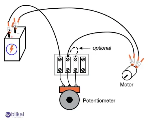
Motor Speed Regulation
A potentiometer is commonly used as a means of input in a DC motor controller, where the speed of the motor is varied. When the wiper is used with a motor driver circuit or PWM controller, the wiper produces a control voltage that determines the speed of the motor. By way of example, clockwise rotation of the knob raises the voltage to the motor driver to spin the motor faster. Such a technique finds broad application in robotics, fan controllers and automation systems.
Analog Input for Microcontrollers (e.g., Arduino)
Analog input devices are common in microcontroller-based projects, such as the use of potentiometers. An example is that a wiper can be connected to an AIN input of an Arduino board to enable the user to change the input voltage range between 0 and 5V. Parameters such as screen brightness, position of the servo motor, or even calibration values on a sensor may be controlled in this manner in real-time. It is an efficient method of providing user interactivity in an embedded system.
Sensor Calibration and Threshold Setting
Potentiometers may be found in instrumentation and sensor use where sensitivity or system parameters such as volts of reference or trigger points are adjusted. By way of example, a light sensor circuit can have a potentiometer to program the desired light level at which a relay operates. This kind of adjustment by hand is useful particularly when prototyping or where the conditions in the field differ, and precise calibration is important.
Joystick and Game Controller Inputs
Some potentiometers, particularly dual-axis models, are integrated into joystick modules. These provide two variable resistances—one for the X-axis and another for the Y-axis. They are used to detect directional movement in game controllers, robotic arms, and pan-tilt camera systems. Wiring both wipers to analog input pins allows for full-range motion detection.
Troubleshooting Wiring Issues
Problem 1: No Voltage Change
Double-check connections. Are the outer pins connected to power and ground?
Ensure the wiper is connected to the correct circuit input.
Problem 2: Output Stuck at One Voltage
The wiper may not be functioning or may be disconnected.
The track inside the potentiometer could be broken.
Problem 3: Inverted Behavior
Swapping Vcc and GND will reverse the direction of adjustment (clockwise vs. counterclockwise).
Problem 4: Potentiometer Gets Hot
This indicates excessive current flow. Potentiometers are not designed for high power—they are signal-level components.
Use a multimeter to test resistance between terminals. As you turn the shaft, resistance between the wiper and each outer pin should vary smoothly.
Frequently Asked Questions (FAQs)
Q1: Can I wire a potentiometer backward?
Yes, however, rotating the knob clockwise will actually lower the voltage output as opposed to raising it. This behavior can be reversed by swapping the outer pins.
Q2: What if I only use two pins of the potentiometer?
By connecting only one of the outer pins and the wiper, it can be used as a variable resistor (rheostat).
Q3: Can a potentiometer be used with AC voltage?
Other potentiometers may deal with AC, but you will need to determine the rated voltage and the type of insulation. The majority of them are Low-voltage DC.
Q4: What resistance value should I use?
It is a matter of application. 1k, 5k, 10k, 100k are common values. In the case of an analog connection to microcontrollers, 10k is usual.
Q5: Can I control high-power loads with a potentiometer?
Not directly. Drive a signal that acts on a transistor or motor driver with a higher current load being controlled by the potentiometer.
Conclusion
It might be easy to understand how to wire a potentiometer, but essential to know how the potentiometer terminals are laid out and also how to understand the voltage-divider characteristic so that the potentiometer can be used properly. Able to offer reliable and low-cost, potentiometers can be used in everything ranging from simple embeds of LED dimmers to much more complex analogs of the control system.
Some images are sourced online. Please contact us for removal if any copyright concerns arise.


