


Soft Start Circuit Guide: Components, Working, and Applications
Introduction to Soft Start Circuits
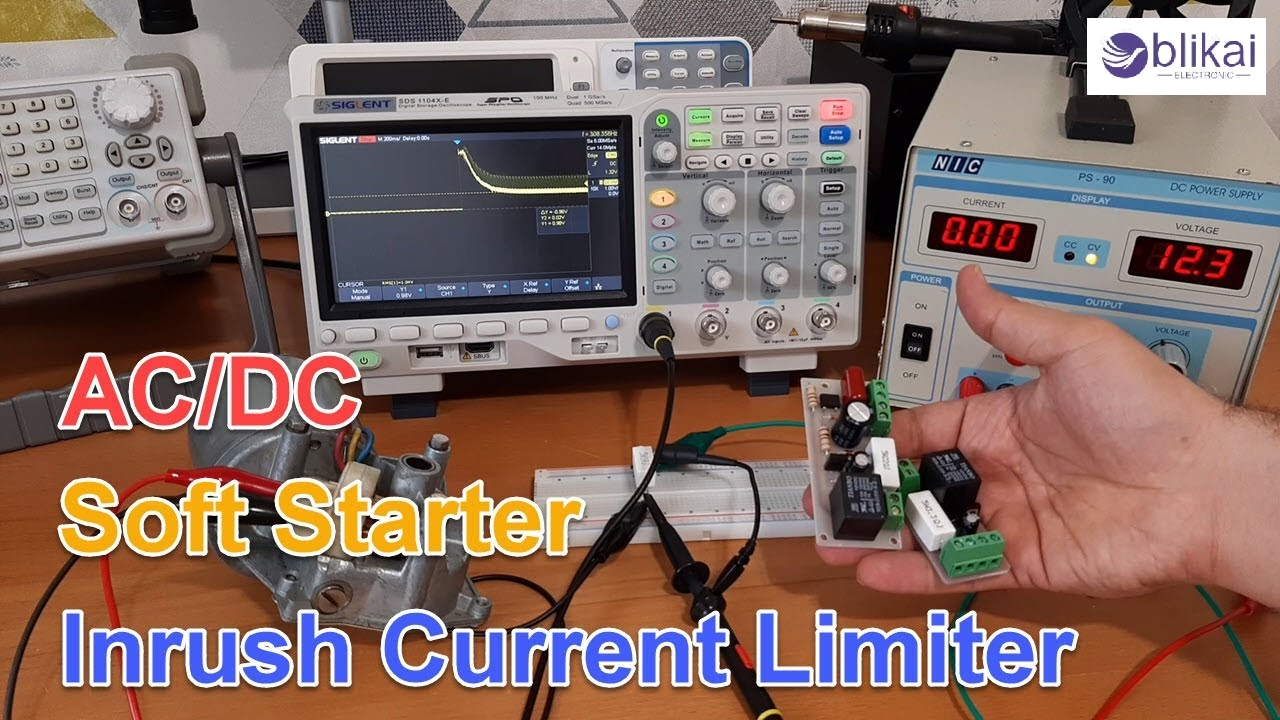
Switching on high-power devices in many electronic and electrical systems often brings a large inrush current that is higher than the usual power used. The increase in power can harm electrical devices, shut them down with circuit breakers and cause their lifespan to be shorter. This function uses a controlled start to lower the large amount of current that can come at the start of powering the unit. It guarantees that voltage or current goes up slowly when the power is turned on. It becomes extremely important to carry out this monitoring in sensitive electronics, large motors, audio amplifiers and switch-mode power supplies (SMPS). Using soft start circuits can ensure that things are safer, more reliable and more efficient in both residential and industrial settings.
How a Soft Start Circuit Works
Soft start circuits are set up to add temporary resistance when turning the power on, which slows the flow of current into the load. Sometimes, the mechanism is based on analog devices such as NTC thermistors, but it can also digitally rely on microcontrollers or ICs. At first, the resistance prevents the current from flowing further when power is given. In time, the thermistor reduces its resistance on its own, or it is done by switching to an alternative path with control logic. Often, the length of the soft start is established with the help of resistor-capacitor (RC) time constants or programmable delay circuits. With the startup stage done, the full operating current goes to the grid.
Core Components of a Soft Start Circuit
A soft start circuit is not difficult, but every part needs to be chosen wisely to manage stress and keep it safe. Important aspects are:
NTC Thermistor: Such a thermistor is highly resistant at first and lowers its resistance as it gets heated by the current flow. It handles the sudden rise in current and changes itself to maintain the flow. The 10D-9 and 20D-11 are widely used types of electric cars.
Relay or Bypass Switch: When the thermistor needs some time before changing, its resistance is low and contributes to power loss. After giving some power to the relay circuit, the device will start without the thermistor in place, allowing it to work at its highest efficiency.
Control Circuitry (Op-Amp, Timer IC, or Microcontroller): An active design relies on an op-amp comparator, 555 timer or microcontrollers such as Arduino or STM32 to control timing.
RC Timing Network: These are used to postpone the change between relays or MOSFETs to control when the circuit starts depending on how the capacitors charge and discharge.
For every component, assessing its voltage, current and load factors is required. The circuit needs proper design to boot up easily and finish a reset during each boot process.
Types of Soft Start Circuits
Depending on complexity and application, soft start circuits can be classified into different types:
Passive Soft Start (NTC-only): The simplest method uses only an NTC thermistor in series with the load. It’s ideal for compact and low-cost designs but may dissipate heat after startup.
Relay-Controlled Bypass: An NTC thermistor is used along with a relay. After a delay (usually a few seconds), the relay shorts the thermistor to remove it from the circuit, improving efficiency.
Active Soft Start with Op-Amps or Microcontrollers: These provide a controlled voltage or current ramp-up. Microcontroller-based designs are programmable and support precise soft start profiles.
SCR/Triac-Based Circuits: For AC motors, silicon-controlled rectifiers (SCRs) or triacs provide gradual voltage control by phase angle modulation. These are used in high-power industrial systems.
Applications of Soft Start Circuits
This type of circuit is applied in several situations to stop the system from facing electrical and mechanical damage:
AC Induction Motors: These are used in elevators, compressors, fans, and pumps. Without a soft start, they draw huge inrush currents that can damage windings or mechanical couplings. Soft start enables smoother motor acceleration.
DC Brushed and Brushless Motors: In electric bikes, drones, or robotics, sudden starts can cause jerky motion or overload power circuits. A soft start ensures smoother speed buildup.
Power Supplies (SMPS): High-capacity switching power supplies can trip fuses or surge protectors at startup. A soft start circuit minimizes peak current during capacitor charging.
Audio Amplifiers: Powering on an amplifier can result in speaker-damaging "pop" sounds due to sudden current surges. Soft start circuits protect both the amplifier and the speaker system.
Lighting Systems and Transformers: High-wattage LED drivers or toroidal transformers benefit from a soft start to avoid overheating and noise.
Designing a Basic Soft Start Circuit
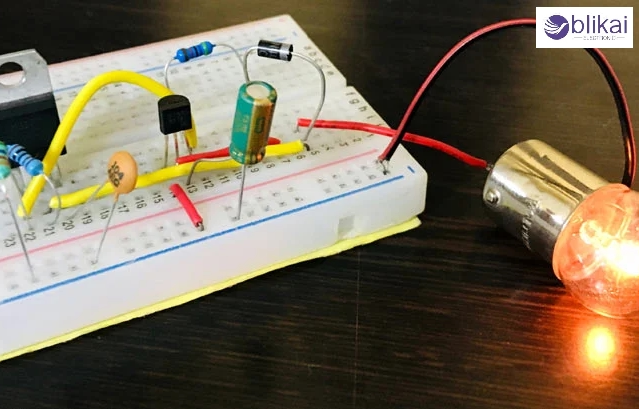
Here is a simple example of how to design a soft start circuit using an NTC thermistor and relay:
Components Required:
- NTC Thermistor (e.g., 10Ω, 5A rating)
- 12V Relay
- Diode (1N4007 for flyback protection)
- Capacitor (100uF–470uF)
- Resistors (1kΩ–10kΩ range)
Working Principle:
When AC power is applied, the thermistor initially limits current. As current flows, it heats up, lowering its resistance. After a predefined delay (set by the RC network), the relay is energized, bypassing the thermistor. A diode across the relay coil ensures protection against voltage spikes.
Tips:
- Choose a thermistor rated for at least 2x the nominal load current.
- Time the relay triggers to 1–3 seconds, depending on load.
- For compact designs, a solid-state relay (SSR) can replace mechanical ones.
Troubleshooting and Testing Soft Start Circuits
Soft start circuits are robust but can fail due to component aging or improper load matching. Common issues include:
Device powers on immediately without delay: The NTC thermistor may be bypassed due to a stuck relay or short circuit.
Overheating of thermistor: Occurs if it’s undersized for the load or lacks a relay bypass. Recalculate power dissipation.
Relay not activating: Check the timing circuit or microcontroller output. Also, test the relay coil and transistor driver.
Testing Tips:
Use a multimeter to measure the cold resistance of NTC: it should be 5–20Ω typically.
Check relay coil resistance and continuity.
Observe voltage across the thermistor during startup; if it remains high too long, the timing delay might be too long.
Periodic inspection helps prevent startup failures or energy inefficiencies.
Advantages and Disadvantages
Advantages:
- Significantly reduces inrush current
- Protects electronic components and relays from surge damage
- Improves system reliability and uptime
- It can be implemented with low-cost components
- Extends equipment lifespan, especially motors and capacitors
Disadvantages:
- Passive NTC designs are less efficient after startup
- Thermal limitations restrict use in continuous-duty cycles
- Requires bypass circuitry for high-load systems
- For complex multi-phase loads, a VFD may be a better option
FAQs About Soft Start Circuits
Q1: Can I use a soft start circuit for any motor?
Yes, but you must select a circuit suitable for the motor type (AC or DC) and match the current and voltage ratings. Induction motors often require SCR-based soft start for phase control.
Q2: Is soft start the same as VFD?
No. A Variable Frequency Drive (VFD) changes both voltage and frequency to control motor speed and torque, while a soft start circuit only controls the initial power-up current.
Q3: How do I select an NTC thermistor for a soft start?
Determine your steady-state current, voltage, and acceptable inrush limit. Select an NTC with sufficient energy handling (Joules rating) and a proper resistance profile.
Q4: Can microcontrollers control soft start?
Absolutely. You can use PWM or DAC outputs to control a MOSFET that regulates the voltage to the load. This gives fine control and is ideal for embedded systems.
Conclusion
Power surges when a system turns on can be easily guarded against using soft start circuits. Adding soft start features to both power tool controllers and motor-driven automation systems can improve how they function, how safe they are to use and their lifespan. After knowing the function and various parts of soft start circuits, both engineers and hobbyists can design better and more energy-saving devices for the tasks at hand.
Related Articles
Current Transformers:Princeple,Types,Application and FAQ
Flexible Alternating Current Transmission System:Working and Types


