


Optimizing Precision with the LTC-2054 [Guide]
What is the LTC2054 Amplifier?
The LTC2054 is an Analog Devices(preliminarily Linear Technology) precision zero-drift functional amplifier. It's well-known for having an extremely low drift value and a large out-of-phase voltage, which makes it perfect for operations taking precise signal exertion.
Key Specifications of the LTC2054 Amplifier
|
Parameter |
Value |
|
Supply Voltage Range |
2.7V to 6V |
|
Input Offset Voltage |
0.5 µV typical, 2 µV maximum |
|
Input Offset Voltage Drift |
0.015 µV/°C typical |
|
Input Bias Current |
1 pA typical |
|
Gain Bandwidth Product |
1 MHz |
|
Supply Current |
800 µA maximum |
|
Common Mode Rejection Ratio (CMRR) |
130 dB typical |
|
Power Supply Rejection Ratio (PSRR) |
140 dB typical |
|
Output Swing |
Rail-to-Rail |
|
Operating Temperature Range |
-40°C to 85°C |
|
Noise Density |
30 nV/√Hz at 1 kHz |
|
Package Options |
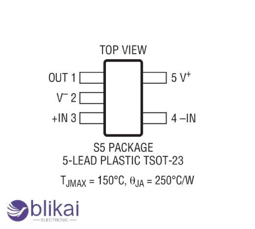
SOT-23, 8-lead MSOP |
Key Features of the LTC2054 Amplifier
- Zero-Drift Architecture
- Low Offset Voltage
- Low Noise
- Rail-to-Rail Input and Output
- Low Power Consumption
- Wide Supply Voltage Range
- High CMRR and PSRR
- Micropower Shutdown Mode
- Small Package
- Temperature Range
Working Principle of the LTC2054 Amplifier
Anover-zero functional amplifier(op- amp) produced by Analog Devices(preliminarily known as Linear Technology) is called the LTC2054. Due to its near- zero neutralize drift and extremely low neutralize voltage, it's the perfect choice for operations taking perfection.
Working Principle:
1. Zero-Drift Architecture:
-The architecture of the LTC2054 is offset drift. Chopper stabilization is another term for this. With this system, the input signal is first modulated to a high frequence, also amplified, and eventually demodulated to return to its original frequence.
-Voltage drift and signal drift are efficiently eliminated by this modulation demodulation procedure. The internal circuitry continuously measures and corrects the input offset voltage by chopping or alternating the signal at a specific frequency.
2. Chopping Mechanism:
-The amplifier consists of two main amplifiers inside: the primary amplifier (which handles the actual signal) and an auxiliary amplifier (which deals with offset correction).
-The input signal is alternately connected to these amplifiers using electronic switches.
-The auxiliary amplifier measures and corrects the offset voltage, while the primary amplifier processes the input signal. By continuously correcting the offset, the op-amp achieves near-zero offset voltage and drift.
3. Input Offset Voltage and Drift:
-The LTC2054 typically has an input offset voltage of a few microvolts and a drift of less than 0.01 µV/°C, making it extremely stable for precision applications.
4. Low-Frequency Noise:
-Low-frequency noise, often known as 1/f noise, is lessened by the chopper's stability, which qualifies the LTC2054 for low noise applications.
5. Power Supply and Operation:
-The LTC2054 operates on a single force voltage(2.7 V to 6V) or binary inventories, making it protean for battery- powered and low- voltage operations.
-It also has a low quiescent current (about 150 µA), which makes it energy-efficient.
Design Considerations of the LTC2054 Amplifier
Power Supply and Grounding:
It's essential to make sure the power force and grounding are proper for the LTC- 2054 in order to maximize its performance. Two power inventories can be used with the LTC- 2054. It's critical to keep tension consistent in order to reduce offset mistakes and boost accuracy. To exclude power force ripple and filter out high frequence noise, power force divorcing capacitors should be deposited near to the intertwined circuit. Accuracy may suffer as a result. Additionally, proper grounding techniques are vital. A star ground configuration, where all ground connections converge at a single point, can help to minimize ground loops and noise interference. Separate analog and digital ground planes may also be used to further isolate noise sources and enhance overall signal integrity.
PCB Layout Guidelines:
Effective PCB layout is fundamental to achieving the high precision required when using the LTC-2054. The placement of the LTC-2054 should be strategically considered to minimize noise and interference. Position the IC near critical components to shorten signal paths and reduce potential sources of error. It is important to keep analog signal traces away from high-current or high-frequency traces to avoid crosstalk. Additionally, maintaining short, direct signal paths and using wide traces can help reduce impedance and signal loss. Properly designed PCB layers with good signal routing and adequate shielding will enhance performance and reliability, ensuring that the LTC-2054 operates within its specified accuracy limits.
Component Selection:
Selecting the right supporting components, such as resistors and capacitors, is critical to optimize the LTC-2054's performance. To keep stability and lower tolerances, high-precision resistors with low temperature coefficients are required. Capacitors need to have great electrical stability and a low equivalent series resistance (ESR) in order to effectively filter and reject noise. The circuit's overall performance may be significantly impacted by the choice of these parts. It has an impact on variables like signal integrity and gain accuracy. It is also crucial to match component values closely to design specifications and consider their tolerance levels to ensure the circuit operates as intended under various conditions.
Optimizing Performance of the LTC2054 Amplifier
Minimizing Offset and Drift:
To achieve optimal performance with the LTC-2054, it is essential to address offset and drift issues, which can significantly impact precision. Calibration techniques are a primary method for correcting offset errors. Regular calibration procedures involve adjusting the circuit to zero out offset voltages and align output readings with expected values. This can be achieved through software adjustments or hardware trim pots, depending on the design. Compensation methods also play a crucial role; implementing circuits that automatically adjust for temperature-induced drift and other environmental factors can enhance long-term accuracy. For instance, using precision reference sources and feedback mechanisms can help to maintain stable performance despite changes in temperature or other variables.
Reducing Noise:
The accuracy of the LTC-2054's filtering technique depends on effective noise reduction. One such method is the use of low-pass filters, which can assist remove high-frequency noise from the signal route. The proper selection and placement of capacitors and inductors are essential for maximizing filter effectiveness and reducing undesired signals. Additionally, employing shielding and isolation practices can further reduce noise interference. Enclosing delicate circuitry to stop external electromagnetic interference (EMI) is known as shielding. Make use of isolation strategies like differential or optocoupler signals. By separating raucous digital impulses from delicate analog circuitry, it preserves signal integrity and lowers errors caused by noise.
Enhancing Stability:
For the LTC-2054 to operate consistently and accurately, stability is a crucial component. One key element in preserving stability is thermal management. Applying heat sink cooling pads or include adequate ventilation in the PCB layout can assist disperse heat and stop heat transfer, which is important because temperature changes impact integrated circuit performance. Consideration of power isolation is another crucial aspect. It is possible to stabilize the power supply and lessen voltage fluctuations by placing specialized bypass capacitors next to the pins of the LTC-2054.
Applications of the LTC2054 Amplifier
- High-Precision Analog Signal Processing
- Medical Instrumentation
- Data Acquisition Systems
- Precision Analog Filters
- Precision Voltage References
- Weighing Scales
- Low-Noise Audio Systems
- Precision Voltage Measurement
- Feedback Loops in Control Systems
- Analog Computation
- Instrumentation Amplifiers
- Data Logging Systems
- Signal Isolation
- Power Supply Regulation
- High-Accuracy Oscillators
- Strain Gauge Measurements
- Precision Analog Meters
Advantages of the LTC2054 Amplifier
- Ultra-Low Offset Voltage
- Low Input Bias Current
- Low Noise
- High Slew Rate
- Wide Bandwidth
- Low Total Harmonic Distortion (THD)
- Rail-to-Rail Output
- High Open-Loop Gain
- Low Input Offset Drift
- Low Power Consumption
- High CMRR (Common-Mode Rejection Ratio)
- Excellent DC Precision
- Wide Supply Voltage Range
What are the key features of the LTC2054?
-Low Offset Voltage: ±5 µV max
-Low Offset Voltage Drift: ±0.1 µV/°C max
-Low Noise: 1.5 nV/√Hz at 1 kHz
-High Open-Loop Gain: 130 dB typical
-High Common-Mode Rejection Ratio (CMRR): 130 dB typical
-Wide Supply Voltage Range: 3 V to 36 V
How does the LTC2054 handle noise and interference?
-The low noise properties of the LTC2054 include low noise intensity, which lessens the interference and noise effects on precise measurements.
In summary, the LTC- 2054 functional amplifier is an exceptional option for a wide range of operations, including medical devices, artificial control systems, and precision dimension systems. Its low offset voltage and lowest drift value characteristics set it apart from other operational amplifiers and set a new standard in precision electronics. The need for high- performance parts like the LTC- 2054 is projected to rise as technology develops. Expanding upon the base set by devices like the LTC- 2054, unborn advancements in functional amplifier technology can concentrate on enhancing perceptivity, dwindling power consumption, and enhancing trustability. To obtain great accuracy and stability in contemporary electronic systems, the LTC-2054 is still a crucial component.
Related Articles
LTC2055 Amplifier:Description,Features & Applications
Voltage Amplifier vs Power Amplifier: What’s the Differences?
Push-pull Amplifier :Overview and Working Principle
What is TL074 Operational Amplifier?


