


RJ45 Pinout: Everything You Need to Know
Setting up an Ethernet network requires a thorough understanding of the pin layout and color code of RJ45 connectors. RJ45 connectors ensure that your network devices communicate properly, whether you're setting up a small home network or a large data center. The purpose of this guide is to provide essential tips to help you master the color coding and layout of RJ45 connectors.
Understanding RJ45 Connectors
Modern networks are incomplete without the RJ45 connector. Our computer, router, and switches all have them, and we never think twice about them. The eight pins and eight wires aren't just for show. Cat5e and Cat6 Ethernet cables are used with these connectors to send data over long distances. Do you want your Wi-Fi to work as fast as possible? Your wired connections are made up of these guys.
However, here's the kicker: wires need to be installed correctly. Does the T568A have better performance than the T568B? The choice isn't based on personal preference. In other words, it's about putting those wires where they should be. All it takes is one wrong move and you're disconnected. Despite its simplicity, the RJ45 can be finicky. In the event that you make any errors in the wiring, you will find yourself staring at a blinking port, wondering what went wrong.
RJ45 Pin Layout
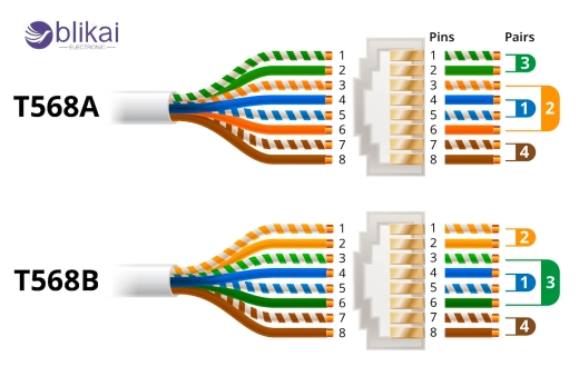
The RJ45 pin layout specifies where the eight pins inside the RJ45 connector will be connected to the corresponding contacts on an Ethernet device. During a network connection, these pins serve as connections for electrical signals. As a result of the layout, data integrity and speed are maintained because the right wire is connected to the right terminal.
Wiring standards T568A and T568B are used in the layout. The wires inside the connector should be arranged in accordance with both standards. Pin layouts, such as those in the T568A standard, begin with white/green (pin 1) and move to white/brown (pin 8). According to T568B, it is white/orange (pin 1) and white/brown (pin 2). Ethernet cable twisted pairs must be aligned with RJ45 connector pins according to these standards. In order to transmit data correctly, pin alignment must be correct; getting it wrong can result in faulty connections or even a complete network failure.
With the clip facing away from you, wire an RJ45 connector from pin 1 to pin 8, starting from the left. In cables, each pin corresponds to a particular wire, whose order determines whether data will be transmitted correctly. It is vital that your wires are positioned according to the standard that you have chosen, in order for your network setup to work properly. In the event of a misplaced wire, a connection may be broken, performance may be poor, or there may not be a connection at all. You can also learn about RJ45 vs RJ11.
T568A vs T568B Wiring Standards
Ethernet cables are governed by two wiring standards, T568A and T568B. At first glance, they appear to be very similar. There are just eight wires with different colored stripes. When you switch around a couple, your internet suddenly behaves as if it's on vacation. Let's get straight to the point, no fluff.
What’s the Difference Anyway?
As part of the TIA/EIA-568 specification, T568A as well as T568B define wiring standards. An RJ45 connector is connected to twisted pairs of Ethernet cables (such as Cat5e or Cat6) by aligning the colored wires inside the cables. What makes the difference? There is a difference between the green and orange wire pairs. That's all. However, it is important.
-
T568A has the green pair on pins 1 and 2.
-
T568B uses the orange pair in that spot.
Switching is simple. Impactful.
Why Do Two Standards Exist?
When the T568A was first introduced, it was the original. A popular choice for residential installations and recommended by the government. In response to this need, AT&T 258A standard was pushed by the telecom industry as a replacement for T568B. Especially in North America, T568B became increasingly popular over time. Nevertheless, both remain in use today.
Which One Should You Use?
The important thing is to be consistent on both ends of the cable, regardless of the cable type you use. A crossover cable (like one you can use to connect two computers directly) can be created by using T568A on one end and T568B on the other. However, what are the most common setups at home and in the office? Ensure that both ends follow the same standard. How many premade Ethernet cables are there? There is a T568B wire running through them. Doing it yourself? It's fine to mix them as long as you know why you are doing so.
RJ45 Pinout Chart
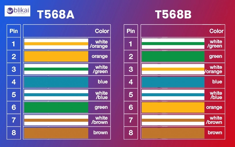
Here is a great visual reference of how to line up the eight wires inside an Ethernet cable with the pins inside an RJ45 connector using the RJ45 Pinout Chart (Visual Table). By showing you instead of telling you "put green here, orange there," you can put the colors correctly. Compared side by side. It's clean. It's clear.
This chart usually includes:
-
Pin numbers (1 through 8)
-
Wire color codes for both T568A and T568B
-
Which twisted pair each wire belongs to
-
What function each pin serves (like transmit, receive)
Faqs
Question 1: Are RJ45 connectors only used with Ethernet cables?
Answer: Most of the time, yes. These sensors are also found in some industrial systems, serial communication setups, and home automation systems.
Question 2: What tools do I need to wire an RJ45 connector?
Answer: Crimping tools, cable strippers, and cable testers are essential. It is also important to have steady hands. There can be a lot of fuss with those tiny wires.
Question 3: What happens if the pinout is wrong?
Answer: If your device is not connected to the network at all, it may not be able to connect. Sometimes, you may experience slow data transfer rates or unstable connections.
Final Thoughts
RJ45 pinouts may seem like a tiny thing-just a bunch of colored wires and a small plastic clip. But man, if you mistakenly connect one pin, all is lost. Network reliability depends on it. It all adds up when you know the difference between T568A and T568B, understand pin layouts, and wire with purpose, whether you're crimping your own cables or just trying to understand what goes on behind the scenes. Don't take chances. Get to know it. Give it a name. Your router will thank you.


