


What are Audio Transformers for?
Audio Transformers function as electromagnetic components that convert and alter input electromagnetic signals into output signals through inductive coupling. Their role involves isolating an input circuit from an output circuit while also filtering signals. Operating within the audible frequency spectrum (20Hz to 20kHz), they find application in various stages: from microphones in the input stage to loudspeakers in the output stage, as well as facilitating coupling and impedance matching of amplifiers. Across these applications, careful consideration of parameters such as frequency response, primary and secondary impedances, and power capabilities is crucial.
Materials and Structure
A transformer serves as an electrical apparatus enabling an input signal, like an audio signal or voltage, to generate an output signal or voltage without direct physical connection between the input and output sides. This function is achieved by utilizing two or more wire coils, referred to as windings, made of insulated copper wire wound around a soft magnetic iron core. In the context of audio transformers, these typically involve copper wire windings around a core composed of steel or a nickel-iron alloy. The choice of core material significantly influences the transmission of electromagnetic signals. Steel, due to its higher hysteresis (lag in magnetic signals), excels in transferring lower frequency signals. Conversely, nickel, with its higher permeability, proves optimal for transmitting higher frequencies. The windings encircling the core define the impedance level, allowing the transformer to increase, decrease, or maintain the signal level as it traverses through the device.
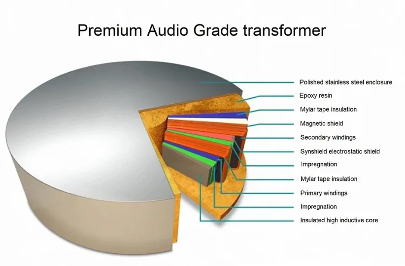
Audio Transformer Structure
Upon entering the transformer via the primary winding, the signal undergoes a transfer to the output secondary winding through the inductive coupling facilitated by the soft iron core. The ratio between the number of coil turns on the primary winding (NP) and the number of coil turns on the secondary winding (NS) defines the "turns ratio." This ratio determines whether the applied signal experiences an increase or decrease as it traverses the transformer.
The turns ratio, governed by the number of wire coils wound around the core, induces either an increase or decrease in the signal strength:
Higher turns on the primary winding compared to the secondary lead to a decrease or "step down" of the signal.
Conversely, greater turns on the secondary winding compared to the primary cause an increase or "step up" in the signal strength.
Audio transformers, akin to power transformers in construction, cater to a spectrum of specialized audio tasks, often multitasking across various functions simultaneously. Unlike transformers primarily wound for specific voltage outputs, audio transformers function predominantly for impedance matching, isolation, and an array of applications (e.g., Data/Voice Coupling Transformers). They are commonly categorized as either step-up or step-down types, serving diverse roles within audio systems.
Matching Impedance
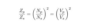
Transformers alter impedance in a manner similar to their adjustment of voltage and current. While they modify voltage through the turns ratio and current inversely to the turns ratio, audio transformers adjust impedance by the square of the turns ratio. Equal voltage is induced within each single coil turn of both windings. Consequently, the primary to secondary voltage ratio (VP/VS) aligns with the turns ratio (NP/NS). In impedance-matching audio transformers, the impedance ratio between windings equates to the square of their turns ratio. In essence, their impedance ratio mirrors the square of their turns ratio and also the square of their primary to secondary voltage ratio.
Impedance relies on the effectiveness of converting voltage into magnetic flux. Audio transformers excel in harmonizing the impedance disparities between amplifiers and loads, ensuring optimal power transfer. For instance, a transformer placed at the amplifier input can align the impedance among microphones, connecting cables, and the amplifier input. Aligning input and output impedance levels ensures efficient power transfer without distortion or signal overload. Impedance-matching transformers share similarities in design with low-frequency voltage and power transformers but operate across a broader frequency spectrum, covering a range such as the voice range from 20Hz to 20kHz.
Isolation or Unity Transformer
Transformers offer a valuable attribute known as isolation. As there's no direct electrical link between their primary and secondary windings, transformers ensure complete electrical isolation between input and output circuits. This isolation feature is also applicable between amplifiers and speakers. A transformer featuring a turns ratio of 1:1 maintains voltage and current levels unchanged while effectively segregating the primary circuit from the secondary side. This specific type of transformer is commonly referred to as an isolation transformer.
With identical impedance for both primary and secondary, the signal level remains unaltered. An audio transformer facilitates the transmission of an audio signal from the primary to the secondary without modification, while effectively obstructing DC voltage and radio frequency interference (RFI). The insulation between primary and secondary circuits enables the transformer to electrically isolate various equipment components, effectively resolving hum issues by isolating or "lifting" device grounds.
Unity transformer applications extend to diverse functionalities, including generating multiple outputs from a single mic input using multiple secondary windings and converting balanced signals to unbalanced ones or vice versa.
Operating across the audio frequency range or even higher for radio-frequency (RF) transformers, audio transformers do present drawbacks. Their wider frequency band contributes to their bulkiness and higher cost. Larger core sizes are necessary as the supply frequency decreases, although specialized core materials can aid in achieving smaller designs. Despite their size and weight in contrast to modern miniature electronics, audio transformers maintain their effectiveness across numerous audio applications. The essence of a transformer lies in its capability to transfer electrical energy between circuits without direct connection, while readily converting energy from one voltage level to another.
100V Line Transformer
An additional type of audio transformer, employed in multi-loudspeaker public address setups, is the 100V line transformer used for linking multiple speakers to a single amplifier. The term "Line" in this context shouldn't be mistaken for the public electricity supply in the United States. In the 100V line speaker system, a transformer elevates the audio output signal voltage to 100V, resulting in low output current for a given power.
By keeping the output current low, the resistance along lengthy cables between the amplifier and loudspeakers attenuates this signal much less compared to maintaining the current at its typical high level. At each speaker, an impedance matching step-down transformer (illustrated in Fig. 11.4.6) is utilized to decrease the voltage, re-escalate the current, and align the line with the low impedance of the loudspeaker.
The primary side's multiple connections enable the selection of an appropriate power level (thus adjusting the sound volume) for each loudspeaker, while the secondary offers various impedance options to match a spectrum of loudspeakers.
Microphone Transformers
Audio transformers serve as effective tools for aligning microphones with amplifier inputs. At the amplifier input, the primary role of a transformer is to match impedance among microphones, connecting cables, and the amplifier input, ensuring minimal signal reduction due to impedance mismatching.
To mitigate electromagnetic interference, particularly low-frequency hum, lengthy microphone cables typically employ a balanced cable design, as depicted in Fig. 11.4.3. These cables consist of two conductors twisted together and enveloped by a conducting shield crafted from metal foil or braid. The twisted conductor configuration helps cancel out the magnetic fields generated by each conductor into the other, while the surrounding earthed conducting foil shields against external magnetic field interferences.
A transformer featuring a single primary and a center-tapped secondary facilitates the connection of a microphone (a two-wire unbalanced device) to the balanced cable. This arrangement places the signals on the two conductors in anti-phase due to the cable being fed from a center-tapped transformer.
At the amplifier input, the difference between these signals results in a doubled amplitude signal. Any externally induced noise in the cable post-transformer appears identical in phase on both conductors, effectively canceling out these noise signals via subtraction at the amplifier input.
This signal combination can be accomplished using either a differential amplifier or a balun (BALanced to UNbalanced) device, which functions as a reversible transformer for matching balanced transmission lines or cables to or from an unbalanced input or output. Fig. 11.4.4 displays a simplified schematic of a balun.


