


74HC164 Shift Register IC: Datasheet, Pinout, Features & Applications
What is the 74HC164 Shift Register IC?
The 74HC164 is an 8-bit serial-in, parallel-out shift register IC widely used in digital electronics for expanding the number of output pins from microcontrollers (like Arduino or ESP8266). It efficiently converts serial data input into parallel output, making it ideal for driving LED displays, controlling multiple devices, and data storage applications.
74HC164 Datasheet Overview
|
Parameter |
Value |
|
Logic Type |
Serial-In, Parallel-Out |
|
Supply Voltage |
2V to 6V |
|
Clock Frequency |
Up to 25 MHz (typical) |
|
Output Current |
±5.2 mA (per pin) |
|
Operating Temp. |
-40°C to +125°C |
|
Package Types |
DIP-14, SOIC-14, TSSOP-14 |
74HC164 Shift Register IC Comprehensive Pinout Guide
Pin Configuration Diagram
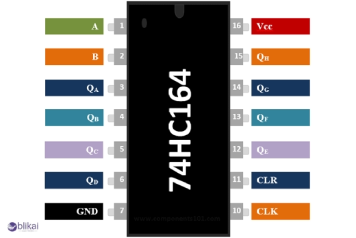
Looking at the 74HC164 shift register from above, you'll notice it comes in a standard 14-pin DIP package. The pins are numbered counterclockwise, starting from the top left corner. Most manufacturers provide a notch or dot to help you identify pin 1. The layout is straightforward, with inputs on the left side, outputs on the right, and power pins at the corners.
Function of Each Pin
Here's what each pin does:
- A & B (Pins 1, 2): Serial data inputs. Both must be HIGH for data to enter the shift register.
- Q0-Q7 (Pins 3, 4, 5, 6, 10, 11, 12, 13): These are your parallel data outputs.
- CP (Pin 8): Clock input – data shifts on the rising edge.
- MR (Pin 9): Master Reset – a LOW signal clears all register stages.
- VCC (Pin 14): Connect to +5V.
- GND (Pin 7): Connect to ground.
Input/Output Characteristics
The inputs have Schmitt-trigger circuits for improved noise immunity. All inputs are CMOS-compatible with typical input capacitance of 3.5pF. The outputs can sink or source up to 25mA (enough to drive LEDs directly) with transition times of about 15ns.
Power Supply Requirements
The 74HC164 requires a clean 5V supply. It draws minimal current – typically just 8μA in static conditions and up to 80μA per MHz during operation.
Recommended Operating Conditions
For reliable operation:
- Keep supply voltage between 2V and 6V (5V is ideal)
- Operating temperature: -40°C to +125°C
- Maximum clock frequency: 48MHz at 5V
- Input voltage levels: HIGH > 3.5V, LOW < 1.5V at 5V supply
- Keep transition times < 500ns to prevent oscillation
Essential Features of the 74HC164
8-Bit Serial-In/Parallel-Out Operation
The 74HC164 does exactly what its name suggests - it takes serial data and outputs it in parallel format. This means you can feed in data one bit at a time and get eight bits out simultaneously. Super handy when you're short on microcontroller pins but need to control multiple outputs.
The serial input comes through two pins (A and B) that can be used in AND or OR configurations depending on your needs. Feed your data bit by bit with each clock pulse, and watch as it shifts through the register until you've got all 8 bits ready at the parallel outputs.
High-Speed CMOS Technology Benefits
The HC in 74HC164 stands for "High-speed CMOS" - and it delivers on that promise. With propagation delays typically under 25ns at 5V, this chip can handle clock frequencies up to 25MHz. That's lightning fast for most hobby projects!
The CMOS technology also means super low power consumption - we're talking microamps in standby mode. No more dead batteries or overheated components.
Noise Immunity and Signal Integrity
Ever had a project mysteriously malfunction due to electrical noise? The 74HC164 helps prevent those headaches with excellent noise immunity. Its CMOS design provides wide noise margins - typically 1.5V at 5V operation.
The chip also includes Schmitt trigger inputs that clean up slow-rising signals and reject noise. This means your data stays intact even in electrically noisy environments.
Clock and Reset Functionality
Need to start fresh? The 74HC164 includes an active-low clear pin that resets all outputs to zero instantly. The synchronous clock input ensures precise timing for your data shifts, with each bit moving on the rising edge of the clock signal.
How the 74HC164 Works
Serial Data Operation
The 74HC164 works on a beautifully simple principle: it shifts data in one bit at a time, and moves all existing bits one position down the line. It's like a digital version of those ticket queues where everyone moves forward one spot when a new person joins.
The shift register has two data inputs (A and B) that work with an AND gate. This means both inputs must be HIGH for a logical "1" to enter the register. If either input is LOW, a logical "0" enters. Most designers connect one input permanently to HIGH and use the other for data, but having two inputs gives you flexibility.
Clock-Based Shifting
Every time the clock input (CP) transitions from LOW to HIGH (the rising edge), magic happens. The data bit waiting at the input gets loaded into the first flip-flop, and all existing bits shift one position right. It's this precise clock-controlled shifting that makes the 74HC164 so useful for expanding outputs or converting serial data to parallel.
Reset Functionality
When you need to start fresh, the active-LOW master reset pin (MR) comes to the rescue. Pull this pin LOW, and all outputs immediately clear to "0" regardless of what's happening with the clock. This reset feature is crucial for initialization or when you need to recover from an error condition.
Applications of 74HC164
Digital Logic Circuits
The 74HC164 shines in digital logic applications where you need to expand outputs or create timing delays. Designers use it to convert parallel data to serial format, ideal when you're short on I/O pins. It's perfect for projects where you need to create sequential binary patterns or implement simple state machines.
LED Displays and Matrix Control
Ever wonder how those scrolling LED signs work? The 74HC164 is often the brains behind them. When controlling LED matrices, this shift register becomes invaluable - just feed in your data serially and watch as it drives whole rows or columns of LEDs with minimal microcontroller pins. This makes it a go-to component for DIY electronic displays, message boards, and lighting projects.
Communication Protocols
The 74HC164 plays a crucial role in implementing serial communication systems. It's commonly used to interface with SPI devices when a microcontroller lacks dedicated SPI hardware. The shift register's ability to convert serial data to parallel output makes it perfect for protocol adapters or extending serial buses.
Home Automation
In home automation systems, the 74HC164 controls multiple devices through a single data line. From smart lighting systems to automated blinds, this shift register can manage multiple outputs while keeping wiring simple. DIY enthusiasts love how it lets them expand their projects without requiring expensive microcontrollers with tons of pins.
74HC164 vs. Other Shift Registers
|
Feature |
||
|
Type |
Serial-In, Parallel-Out Shift Register |
Serial-In, Parallel-Out with Storage Latch |
|
Output Control |
Direct parallel output (no latch) |
Latched outputs (prevents flickering) |
|
Cascading |
Possible, but no built-in serial-out |
Supports daisy-chaining (serial-out pin) |
|
Reset Function |
Master Reset (MR) pin (Active LOW) |
No dedicated reset pin (requires manual clearing) |
|
Voltage Range |
2V – 6V |
2V – 6V |
|
Clock Speed |
Up to 25 MHz |
Up to 25 MHz |
|
Output Current |
±5.2 mA per pin |
±6 mA per pin |
|
Package Options |
DIP-14, SOIC-14, TSSOP-14 |
DIP-16, SOIC-16, TSSOP-16 |
|
Best For |
Simple LED driving, static displays |
Dynamic displays (e.g., multiplexed LEDs) |
|
Price |
Lower cost |
Slightly higher cost (due to latch) |
Troubleshooting and Performance Optimization
Common Issues and Solutions
Getting weird outputs or no output at all with your 74HC164? The most common culprit is incorrect power supply voltage. The 74HC164 needs a clean 2-6V supply. Too low and you'll get unreliable operation; too high and you risk damaging the chip.
Clock signal problems trip up many engineers. Remember the shift register only responds on the rising edge of the clock. If your clock signal is noisy or has slow rise times, data won't transfer properly.
Bad wiring is another headache. Double-check those connections! A floating input can cause unpredictable behavior since CMOS inputs should never be left unconnected.
Testing Procedures
Got a shifty shift register? Here's how to test it:
- First, set up a basic circuit with LEDs on each output. Apply power, hold the clear pin high, and feed a "1" into the data input while pulsing the clock. Watch as your "1" propagates through each output.
- For more thorough testing, connect the shift register to a microcontroller and create a test pattern that exercises all functions. Try shifting in alternating 1s and 0s, or counting patterns.
- Use an oscilloscope to verify signal integrity, especially if you're running at higher frequencies. Check for ringing, slow rise times, or noise that could cause false triggering.
Enhancing Reliability in Noisy Environments
Industrial settings can be brutal on digital ICs. Here's how to protect your 74HC164:
- Add 0.1μF ceramic decoupling capacitors right at the power pins. This filters out noise that could cause erratic operation.
- For really noisy environments, consider optoisolators for your inputs. They provide excellent electrical isolation and noise immunity.
- Signal lines should be kept short, especially clock lines which are susceptible to noise pickup. If you need long runs, use twisted pairs or consider differential signaling.
- Ground planes help enormously with noise reduction. Make sure your ground connections are solid and use a star grounding approach when possible.
Conclusion
The 74HC164 shift register stands as a versatile and powerful component in digital circuit design, offering an elegant solution to pin limitations and serial-to-parallel data conversion challenges. Throughout this guide, we've explored its pinout, distinctive features, operational principles, and practical applications from LED display control to data conversion. We've also examined how it compares to other shift registers and demonstrated its integration with popular platforms like Arduino.
Related Articles
MAX3232 IC: Pin Configuration, Features its Applications
LM339 Comparator IC: Features, Specifications & Applications
CD4035 Shift Register: Features, Specifications and Applications


