


How to Calculate Coupling Capacitor Value
Have you ever wondered why your audio system sounds distorted or why your signal processing circuit isn't functioning as expected?
Understanding Coupling Capacitors
The coupling capacitors are integral components of electronic circuits that permit alternating current signals to be coupled between different circuit stages while they block direct current voltages. Their main function is to remove DC bias voltages between circuit stages and to allow Alternating Current through them. This functionality is crucial in audio amplifiers, communication systems, and various other electronic applications.
Types of Coupling Capacitors
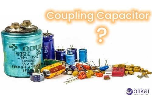
There are many types of coupling capacitors, with their characteristics and uses:
- Ceramic capacitors: They are perfect for radio frequencies due to their low inductance.
- Film capacitors: Offer excellent stability and are suitable for audio circuits.
- Electrolytic capacitors: Build compact capacitance in low-frequency applications.
- Tantalum capacitors: Their high capacitance to volume ratio provides a reliable circuit.
Importance in electrical circuits
Coupling capacitors are applied to maintain the quality of signals and performance of the circuit, since they will not allow DC voltage levels to interfere with the next stages. It is therefore very important in achieving proper AC characteristics desired from the signal. By blocking DC and allowing AC to pass, coupling capacitors enable efficient signal transfer between circuit stages, reduce distortion, and improve overall system performance.
Factors Affecting Coupling Capacitor Value
A. Input and output impedance
Understanding the input and output impedances of the connected circuits is crucial when calculating coupling capacitor values. These impedances directly influence the capacitor's ability to transfer signals effectively. Higher impedances generally require larger coupling capacitors to maintain signal integrity across the desired frequency range.
B. Frequency range
The frequency range of the signal being coupled is a critical factor in determining the appropriate capacitor value. For use in lower frequencies, larger capacitance values are required to ensure adequate signal transfer, while in the higher frequencies, smaller capacitors may often be used. Care should be taken to consider the lowest frequency of interested coupling capacitor value so that one will not lose signal strength at the low end.
C. Signal amplitude
The amplitude of the signal being coupled also plays a role in capacitor selection. Larger signal amplitudes may require capacitors with higher voltage ratings to prevent breakdown. Additionally, the capacitor's value should be chosen to minimize distortion, especially for high-amplitude signals in audio applications.
D. Circuit topology
The overall circuit topology, including the presence of other components and their interactions, affects the choice of coupling capacitor value. Factors such as feedback loops, impedance-matching networks, and filtering requirements can all influence the optimal capacitor value. It's essential to consider the entire circuit design when selecting coupling capacitors to ensure proper functionality and performance.
Step-by-Step Calculation Process
A. Determine the lowest frequency to be passed
To begin the calculation process for coupling capacitors, it's crucial to identify the lowest frequency that needs to be transmitted through the circuit. This frequency serves as the foundation for subsequent calculations and ensures that the capacitor can effectively couple signals across the entire desired frequency range.
B. Calculate the reactance at the lowest frequency
With the lowest frequency established, the capacitive reactance must be determined on this frequency. This step is necessary to make sure that the coupling capacitor has very little effect at the low frequency of interest.
C. Consider the load impedance
The load impedance is important in solving for the right coupling capacitor value. It certainly becomes necessary to analyze the impedance of the circuit or component to which the capacitor will be coupled, since it influences the entire behavior of the coupled system.
D. Apply the coupling capacitor formula
All the specified parameters are now at AAA's disposal, thus they will be plugged into the respective coupling capacitor expression to get the desired capacitance. This formula typically involves the lowest frequency, desired reactance, and load impedance. The result will give you the minimum capacitance needed for effective coupling.
E. Adjust for practical considerations
Finally, it's important to fine-tune the calculated value based on practical considerations. This may involve rounding to standard capacitor values, accounting for tolerance ranges, or considering other circuit-specific factors that could influence the capacitor's performance.
Tools and Resources for Calculations
Online calculators
When coupled with the computing capabilities afforded by the calculator, calculations for coupling capacitors are truly doable and enjoyable. The finding function is often much better and quicker than a manual interaction. Most of the noteworthy electronics websites have developed their coupling-capacitor web calculators for free, allowing the loading of parameters such as frequency, impedance, and desired cutoff. These tools are generally easy to operate and give instant results, which make them appropriate for technicians and engineers alike.
Spreadsheet formulas
For those who prefer more flexibility and customization, spreadsheet formulas offer a powerful alternative. Programs like Microsoft Excel or Google Sheets can be used to create your coupling capacitor calculator. By inputting the necessary equations, you can build a reusable tool that allows for easy adjustment of variables. This method is beneficial for batch calculations or when you need to maintain a record of your design process.
Mobile apps for quick calculations
Mobile phone apps are the latest tools used to quickly run the necessary calculations while you continue juggling your tasks. Consider several apps that cater only to electronic engineering computations; some even include coupling capacitor value determinations for iOS and Android. They share most of the easy-to-use features of online calculators while remaining mobile and, therefore, perfect for fieldwork or a fast inquiry during design meetings.
Practical Examples and Applications
A. Audio coupling in amplifiers
In audio amplifiers, coupling capacitors play a crucial role in separating DC bias voltages between stages while allowing AC audio signals to pass through. For example, in a guitar amplifier, a coupling capacitor often connects the preamp with the power amp stage. The capacitance value is then chosen large enough to allow passing of the lowest frequencies of interest (about 20 Hz) without significant attenuation. A good working capacitance for general purposes here would be between 0.1 μF to 1 μF.
B. DC blocking in RF circuits
In radio-frequency (RF) circuits, DC blocking is often desired to avoid various DC voltages interfering with signal transmission. An example is the radio transmitter, which has a coupling capacitor used between the power amplifier and antenna to block any DC while allowing the RF signals to pass through. The values of the capacitor in this case will depend on the frequency the circuit operates at, and lower values (say 100 pF to 1 nF) are typically devoted to higher frequencies to reduce parasitic effects.
C. Interfacing between stages in signal processing
Coupling capacitors are necessary in digital signal processing circuits for interfacing various stages with one another. For example, they can be used between the sensor output and the ADC input of microcontrollers to ensure any DC offsets produced by the sensor do not affect the readings from the ADC. A good range of capacitance for this would be somewhere between 0.1 μF and 10 μF, based on the characteristics of the sensor and controller.
Conclusion
When working with coupling capacitors, it is important that the value be calculated correctly for optimal signal transfer. Factors such as frequency range, impedance matching, and source/load characteristics can be considered for efficient designs. The step-by-step process explained in this guide, with the recommended tools and resources, forms a sound basis for outputting correct results.
In this case, one must be very careful about not neglecting common pitfalls, such as parasitic effects and temperature variations. As you apply these principles to your projects, refer back to the practical examples provided to reinforce your understanding. With practice and attention to detail, you'll confidently select the ideal coupling capacitor values for your electronic designs, enhancing overall system performance and reliability.
Related Articles
What Is CBB61 Capacitor - Function and Applications
Capacitor Symbol: What Does It Really Mean?
What is Tantalum Capacitor: Design, Construction and Applications
Capacitor Tester: Types, Applications & Advantages
How to Test a Capacitor: Simple Steps and Tools
How to Test a Capacitor with a Multimeter [Guide]


