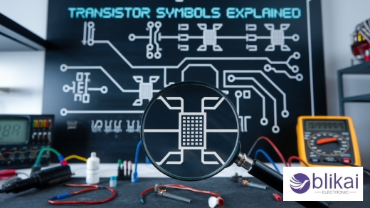
Transistor Symbol Explained: Understanding the Basics and Types
What is a Transistor?
A transistor consists of three interspersing layers of semiconductor, generally silicon. A transistor can be allowed as an amplifier or a switch within electronic circuits. Transistors are used to regulate the inflow of electric current, whether amplifying weak signals or acting as an on-off switch in our digital electronic circuits.

Understanding the Transistor Symbol
Basic Structure of a Transistor Symbol
The symbol for a transistor has three corridors: the base, the emitter and the collector. The lines and shapes connected with each part indicate the function and their connection in the device. Depending on the type of transistor, which we will refer to as a PNP or NPN until we get further in our contact, the emitter is depicted by an arrow that indicates direction either in or out. The base is a short line perpendicular to the emitter, and the collector represents the longer line parallel to the feeder.
Significance of Arrow Direction
The arrow direction in transistor symbols is pivotal in understanding the geste of the transistor device and proper transistor connection in circuits. The arrow indicates the type of maturity charge carriers in the transistor(electrons or holes) and the conventional current direction. This information is vital in generating a proper bias for the transistor within the colorful circuits to serve duly.
Types of Transistor Symbols
Bipolar Junction Transistor (BJT) Symbol
The symbol is a circle with three lines: emitter, base, and collector. The emitter generally has an arrow indicating the direction of the current flow. The arrow points in for NPN and out for PNP.
Field-Effect Transistor (FET) Symbol
In discrepancy to BJTs, FETs have different symbols. The symbol of the FET is generally a perpendicular line representing the channel with three leads, which are considered the source, gate, and drain. The gate of Junction FET(JFET) has an arrow pointing towards the channel, indicating N-channel, and an arrow pointing down, indicating P-channel.
MOSFET Symbol
The MOSFET symbol will look like the FET symbol, but it will have some modifications. Instead of a continuous vertical line for the channel, there will be a broken vertical line, and the source and drain connections will include a separate horizontal line for the substrate connection as well. The gate is generally represented by a horizontal line that does not touch the vertical channel to indicate the insulating oxide layer.
Phototransistor Symbol
Phototransistors, which are transistors that respond to light, are represented uniquely. The symbol looks like a BJT symbol, but two arrows point toward the device to indicate light coming in. The symbol visually communicates important characteristics of the transistor to show that it reacts to light and conducts current depending on the light levels.
How to Read Transistor Symbols
Understanding the Components
In order to read the symbol of transistors, you must be able to identify the main corridor of the transistor. The three main factors of the transistor symbol are the emitter, base, and collector. The emitter is generally represented by an arrow that is constantly seen atop the emitter connection. The base is a short line that is perpendicular to the body of the symbol. The collector is shown as a longer line parallel to the emitter.
Identifying Transistor Types
The arrow's direction in this symbol indicates the type of transistor you're dealing with. However, also this is an NPN transistor; if the arrow is directed down from the base, it's a PNP transistor, If the arrow is directed toward the base.
Interpreting Additional Elements
Certain transistor symbols may have varying components that help convey additional intention. For example, a circle symbolizes a transistor that is encased in metal. You may also see symbols that contain more than one emitter or collector to designate special types of transistors.
Recognizing Orientation
The exposure of the transistor symbol in relation to the rest of the circuit conveys some meaning. Generally, the emitter is at the bottom, the base is in the center, and the collector is at the top. While this is usually true, the exposure of the emitter, base, and collector can be different depending on the circuit and/ or the developer's choice.
Reading Transistor Symbols in Circuit Diagrams
Understanding Circuit Context
Generally, transistors work with other circuit factors, and their part in operation depends veritably much on those factors. To determine the function of a transistor, examine the connections that go from the transistor to other circuit factors, e.g., resistors, capacitors, and voltage sources. It's in these connections that you will be able to determine the function of the transistor as an amplifier, as a switch, etc., as part of a specific circuit.
Identifying Biasing Configurations
An important part of reading transistor symbols in diagrams is to find some common biasing configurations. Look for patterns that indicate some specific configurations, like common emitter, common collector, or common base configurations. Each of these has its characteristics and purpose in a circuit. For example, a common emitter configuration could feature a voltage divider network to the base, and a common collector might have the collector tied directly to the power supply.
Recognizing Feedback and Signal Paths
Schematics and circuit drawings often have feedback paths or signal paths that include transistors. Once you identify the diagrams, you can trace the feedback or signals path through the transistor and identify if feedback exists. This will help improve your understanding of the overall circuit behavior (i.e., gain, oscillation, etc.).
Transistor Applications
Diverse Applications
Transistors are the hidden champions behind the scenes, serving countless uses in modern electronics. Transistors are employed in computers, as they serve as the main building blocks in microprocessors that carry out all necessary calculations in a fraction of a moment, allowing advancements in the digital world. Microprocessors are the primary component in everything from smartphones to supercomputers, where millions of transistors calculate and store information.
Power Management
Transistors are particularly good for managing power consumption. As an illustration, they serve the purpose of voltage control to deliver a fixed output supply to the electronic devices' components. Furthermore, solar inverters are used to convert the direct current (DC) produced by solar panels to alternating current (AC) to utilize household energy.
Sensor Technology
Transistors are a crucial element in sensor technology. They're employed in temperature sensors, light sensors, and pressure sensors, where they can convert physical marvels into electrical signals. This capability is important for numerous diligence, including automotive health and heartiness. Transistors enable perfection measures and responsive systems.

Common Mistakes When Interpreting Transistor Symbols
Misidentifying Transistor Types
A frequent error in reading transistor symbols is misattributing the type of transistor. Newbies frequently confuse bipolar junction transistors(BJTs) with field-effect transistors(FETs) because they look likewise in circuit plates. You can avoid this by precisely checking the arrow direction and checking for or not having a gate terminal.
Confusing Collector and Emitter
Another common mistake regards the collector and emitter terminal connections in BJT symbols. Keep in mind that the arrow points toward the emitter in NPN transistors, but it points away from the emitter in PNP transistors. This distinction is very important in circuit analysis and design.
Overlooking Doping Type
Sometimes, engineers overlook the doping referenced in the transistor symbol. Note that the BJT symbol indicates not only the current direction but also shows whether it is an NPN or PNP transistor. This mistake can be trivial, but the circuit may behave unexpectedly when the misreading of the doping type becomes apparent.
Ignoring Substrate Connection
In integrated circuits, transistor symbols may include a fourth terminal representing the substrate connection. Overlooking this can result in incomplete circuit analysis, especially when dealing with more complex semiconductor devices.
Misreading MOSFET Symbols
MOSFET symbols can be particularly tricky. A frequent error is to misread either the bulk (body) terminal or to mix up enhancement-mode and depletion-mode MOSFETs. Make sure that you read the nuances of the symbol correctly and compare it to standard references so that you are interpreting them accurately.
Related Articles
Resistor Transistor Logic (RTL): Operation, Variations, Traits & Uses
13009D Transistor: Applications, Equivalent and Specifications
Transistor Series Voltage Regulator:All You Need to Know
MPSA92 Transistor: Pin Configuration and Applications
TIP31C NPN Transistor: Working Principle and Applications
2N5306 Transistor: Features and Application
What is BC547 Transistor: Applications and Working Principle
2N7000 Transistor: Applications, Features and Datasheet
IRF540N Transistor: Applications, Datasheet and Features
Types of 547 Transistors:All Explained
2SC5200 Transistor:Pinout and Applications
PN2222 Transistor: Equivalents, Applications and Features
2N3904 Transistor: Features, Applications and Datasheet


