


What is Phase Splitter ?All You Need to Know
A phase splitter or phase inverter refers to the polarity of the current and is simply made by using different types of amplifiers or optimizing a transformer to efficiently divide currents. These are widely utilized in the music instrument and manufacturing industries for controlling power output. One of the simpler methods to create this device is by employing a transformer. This article provides brief information on a phase splitter, its working principles, types, and applications.
What is a Phase Splitter?
A device used to divide a single-phase current into two or more currents varying within a phase is known as a phase splitter. Sometimes, it is necessary to supply two signals that are equal in amplitude but 180 degrees out of phase with each other. These two signals can be derived from a single input signal using a phase splitter, which is employed to run a single-phase induction motor. The term “phase splitter” is most frequently associated with amplifiers that generate two balanced voltage outputs of equal amplitude but with reverse polarity. It is also occasionally used for generating quadrature signals.
How Does a Phase Splitter Work?
The phase inverter operates quite simply across all tube amplifier circuits. It accepts a signal input and produces two outputs: one that is identical to the original (in-phase) and another that is the mirror image (phase-inverted/flipped phase). In this process, no signal amplification is necessary, and the phase splitter usually maintains unit gain, merely altering the phase. Each signal drives a power tube connected to each side of the primary winding of the output transformer in the push-pull configuration.
Phase Splitter Circuit
A phase splitter circuit is employed to produce two output signals of equal amplitude but opposite phases from a single input signal. This represents another type of BJT configuration where a single input sinusoidal signal is divided into two outputs that are 180 degrees out of phase with each other.
An example of a phase splitter circuit using a single transistor is shown below. This circuit combines the characteristics of a common emitter (CE) amplifier with a common collector (CC) amplifier. The circuit in the CC and CE amplifier configuration is forward-biased to operate as a linear class-A amplifier, minimizing output signal distortion.
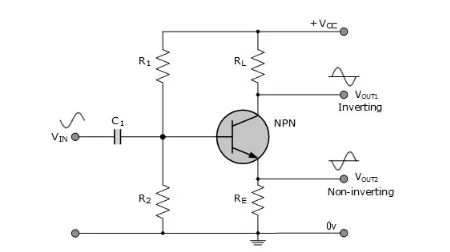
By merging the common emitter and common collector amplifier setups and extracting signals from both the emitter and collector terminals concurrently, we can devise a transistor arrangement that yields two output signals of equal amplitude but opposite in direction.
Operation of Phase Splitter
The phase splitter circuit, constructed with a single transistor to produce inverted and non-inverted outputs, is depicted below. In this setup, the input signal is fed to the base terminal of the transistor, with one output derived from the collector terminal and the second from the emitter terminal. Consequently, the transistor-based phase splitter circuit functions as a dual-output amplifier, generating complementary outputs from both the emitter and collector terminals that are 180 degrees out of phase.
In the common emitter (CE) amplifier, the voltage gain is determined by the ratio of RL to RE, expressed as -RL/RE. Here, the negative sign signifies an inverting amplifier. If both resistor values are made equivalent, such as RL = RE, the voltage gain of the common emitter stage becomes unity, or -1.
In the common collector (CC) amplifier, the emitter follower amplifier circuit inherently exhibits a non-inverting voltage gain close to unity (+1). The two output signals from the emitter and collector terminals maintain equal amplitude but are 180 degrees out of phase. Thus, the phase splitter circuit proves highly advantageous for delivering anti-phase or complementary inputs to another amplifier stage, such as a class-B push-pull power amplifier.
To ensure proper operation, the voltage divider network connected across the supply rail and ground must be carefully chosen to stabilize the DC states, enabling symmetrical output voltage swing from both transistor terminals.
Types of Phase Splitters
Various types of phase splitters are elaborated upon below.
Cathode-Coupled Phase Splitter
One of the most frequently employed phase splitters is the cathode-coupled phase splitter, prized for its straightforward design and remarkable effectiveness. This configuration, utilizing a single tube, offers a simple means of phase division. However, it comes with trade-offs such as slightly sub-unity gain and limited headroom. In this setup, output signals are constrained from swinging beyond ground level, and the tube may also dissipate a portion of the supply voltage due to resistor loading. The cathode-coupled phase splitter finds application in numerous popular guitar amplifiers, including push-pull designs, many Orange amps, and various Ampegs.
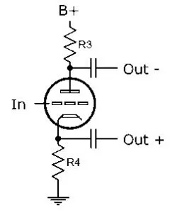
Whenever the input signal of this phase splitter dips into negativity, the valve will reduce its conduction, leading to a decrease in current flow. Consequently, the voltage decline across the two load resistors in the setup also diminishes, resulting in a drop in cathode voltage whenever the anode voltage rises. Conversely, when the input signal swings positively, the opposite effect takes place. The output from the anode undergoes inversion, whereas there is no inversion at the cathode terminal. When an equal current flows through both loads, the signals produced across them will be identical but with a 180-degree phase shift.
Paraphrase Phase Splitter
The paraphrase phase splitter represents the most basic and earliest form of this technology. It serves to divert the primary signal path while introducing an additional amplification stage, resulting in inversion. The term "para," meaning "side by side," illustrates how the circuit creates a new path parallel to the original one. However, the term "paraphrase" historically refers to other types of phase inverter circuits.
Compared to the cathode, the paraphrase phase splitter preserves more headroom and requires only one or two extra resistors. However, matching the gain and output impedance of the two phases can be challenging, making it less common in hi-fi circuits but a compelling choice, especially in guitar amplification. Its configuration makes direct coupling difficult, limiting the use of negative feedback.
Long Tail Pair
The long tail pair phase splitter enjoys popularity in push-pull hi-fi setups. It maintains ample headroom and offers voltage amplification. Its output impedance is largely equivalent, with the only caveat being that the "tail" should be sufficiently long for optimal performance.
In this setup, the first triode resembles a grounded cathode amplifier. The second triode, with its grid grounded, receives signal input from the cathode, thereby avoiding inversion at its anode. The shared cathode load serves as the "tail" and is crucial for achieving balance.
Typically, a higher tail impedance results in better matching of output impedance and gain for this splitter. However, its main drawback lies in the additional components required, including an extra triode, CCS (constant current source), and negative rail, making it more complex compared to other phase splitters.
Advantages & Disadvantages
The pros of a phase splitter are as follows:
Phase splitters boast straightforward design.
They can be directly connected to the preceding stage.
They exhibit high linearity.
Adjustment and stability are easily achieved.
They produce minimal distortion.
They offer substantial gain.
They deliver high-amplitude output signals.
They possess low output impedance.
The cons of a phase splitter are as follows:
Phase splitters have lower gain.
They are highly sensitive to the load.
Their linearity is compromised by internal capacitances within the tube, which differ between the grid and the plate or the grid and the cathode, though these discrepancies are typically minimal and remain outside the audio range.
The tubes used in the splitter must be matched pairs from a twin tube.
Quality heavily relies on the transformer used.
Applications/Uses of Phase Splitter
The uses of phase splitter include the following:
A phase splitter is crucial in push-pull audio amplifiers.
The DC-balanced phase splitter is commonly used in audio applications such as pre-amplifiers and power amplifiers.
A phase splitter circuit takes an input signal and divides it into two identical but opposite phase signals.
In practical applications, phase splitters are employed in the manufacturing industry to control the speed of electrical motors in various industrial machines. They are also utilized in the music instrument industry to amplify power for sound equipment.
Using phase splitters in the industrial sector significantly reduces power conversion costs.
It is an essential component in audio and electrical engineering, separating a single signal into multiple phases to enable balanced power distribution and enhance sound quality in stereo systems.
A phase splitter is an electronic circuit used in signal processing, serving multiple functions.
The two output signals from a phase splitter drive a push-pull amplifier configuration, improving the amplifier's efficiency and reducing distortion.
They are used in audio applications.
A phase shifter circuit alters the phase of an input signal by a specific amount.
A phase shifter adjusts the phase relationship between different signals or creates specific phase shifts for signal processing applications.
Phase shifters are commonly used in communication systems, such as radio frequency applications.
They drive an amplifier within a balanced topology, such as an H bridge or push-pull.
They are used to drive balanced audio cables or balanced transmission lines.
They supply voltages within an oscilloscope to deflection plate pairs inside the CRT.
They generate anti-phase signals used in some filter designs, such as all-pass filters for approximate quadrature signals in SSB signal generation or old quadraphonic decoders.
Sumarry
Thus, this is an overview of phase splitters, including their circuit, working principles, types, advantages, disadvantages, and applications. A phase splitter is a device that divides a signal into various phases. It alters the phase of an AC signal and generates outputs with 90-degree and 180-degree phase shifts from the input. Here is a question for you: what is another name for a phase splitter?
Related Articles
Strain Gauge : Principle and Its Applications
PNP Transistor? Construction, Working & Applications
Insulated Gate Bipolar Transistor:Features and Pinout
What is Phase Splitter ?All You Need to Know


